Reverse engineering inverter to light up a LCD Backlight bulb without a laptop
This is a follow up to the Turn a Broken Laptop Screen Into a Portable Light Table for Drawing

Hope this can get you some hints on how to reverse engineer part of the circuit in order to find its pinout, because every board is a little bit different.
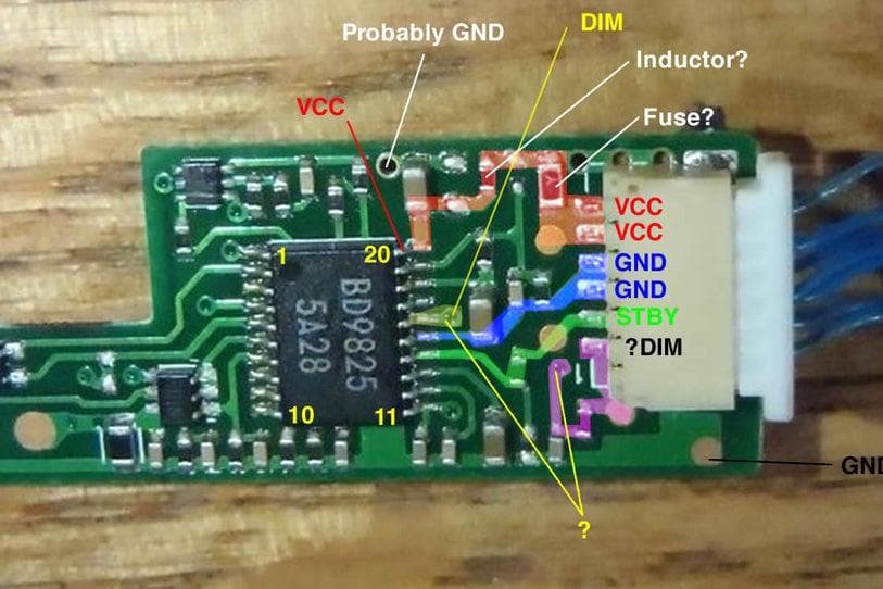
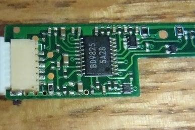
This is a picture of a inverter board a user asked on the comments.
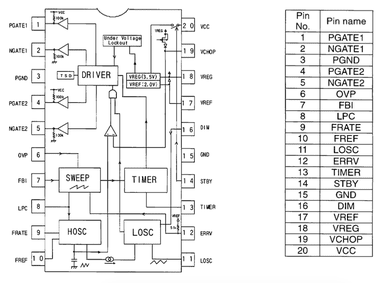
He sent a picture of his board. The main device is this BD9825, search for it on google followed by the keyword "datasheet", what you're looking for it is a PDF document containing all the information about this chip.
http://pdf1.alldatasheet.com/datasheet-pdf/view/13...
The data sheet contains a description of each pin. Look at your board, the chip should contain a marking on one of the 4 corners a little dot indented, or a U groove in one side. This indicates pin 1. To make things easier rotate your board and orient this on your top left. Then count the pins counter-clock wise.
   ___  __
1-| * \/  |-6
2-|       |-5  This is how you would orient and count pins on a chip.
3-|_______|-4
The easiest is always to find what is the GND (Ground) pin. The data chip specify GND as pin 15, count the pins and find out which pin is the 15, then follow the trace coming out this pin until it reaches one of the pins on the connector on the side, then now you know what this pin is GND. If it goes to a via follow it on the other side, if it goes underneath something you can't see were it goes, the make you best guess were it pokes out, the use a multimeter to check continuity to know if your assumption was correct.
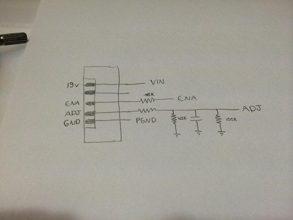
I did basically the same with the other pins.
The GND should be very straight forward from the pin to the connector, using large traces, or ground planes, and maybe attached to multiple pins.
VCC should be a thicker trace as well, should contain one or more bypass capacitors (beige retangular devices with 2 pads) across VCC and GND, may have a in series inductor (looks like a black rectangle probably without a number on it, you multimeter should read near zero ohms if it is a inductor), and may contain a fuse in series (there are black, white, or green fuses, but should read 0 ohms).
The other Enable/Standby Adjust/Dim pins should be thinner traces coming out of the IC and will probably contain a resistor/capacitor network, to make it simpler just follow the board traces, if the traces ends on a component, continue following the trace after the resistors (black ones, with 3 digits on it) not the capacitors (yellowish ones), the capacitors will probably end to ground.
This board was different than mine, it has a STBY instead of ENABLE, and DIM instead of ADJ, but this shouldn't make much difference apart from labeling. But the data sheet is not very clear about what the levels are for DIM.
The VCC voltage should be the same as the stock power supply of the laptop it came from.
