Turn a Broken Laptop Screen Into a Portable Light Table for Drawing
Posted originally on Instructables Published Jul 8th, 2014

[https://www.instructables.com/Turn-a-broken-laptop-screen-into-a-portable-light-/](https://www.instructables.com/Turn-a-broken-laptop-screen-into-a-portable-light-/)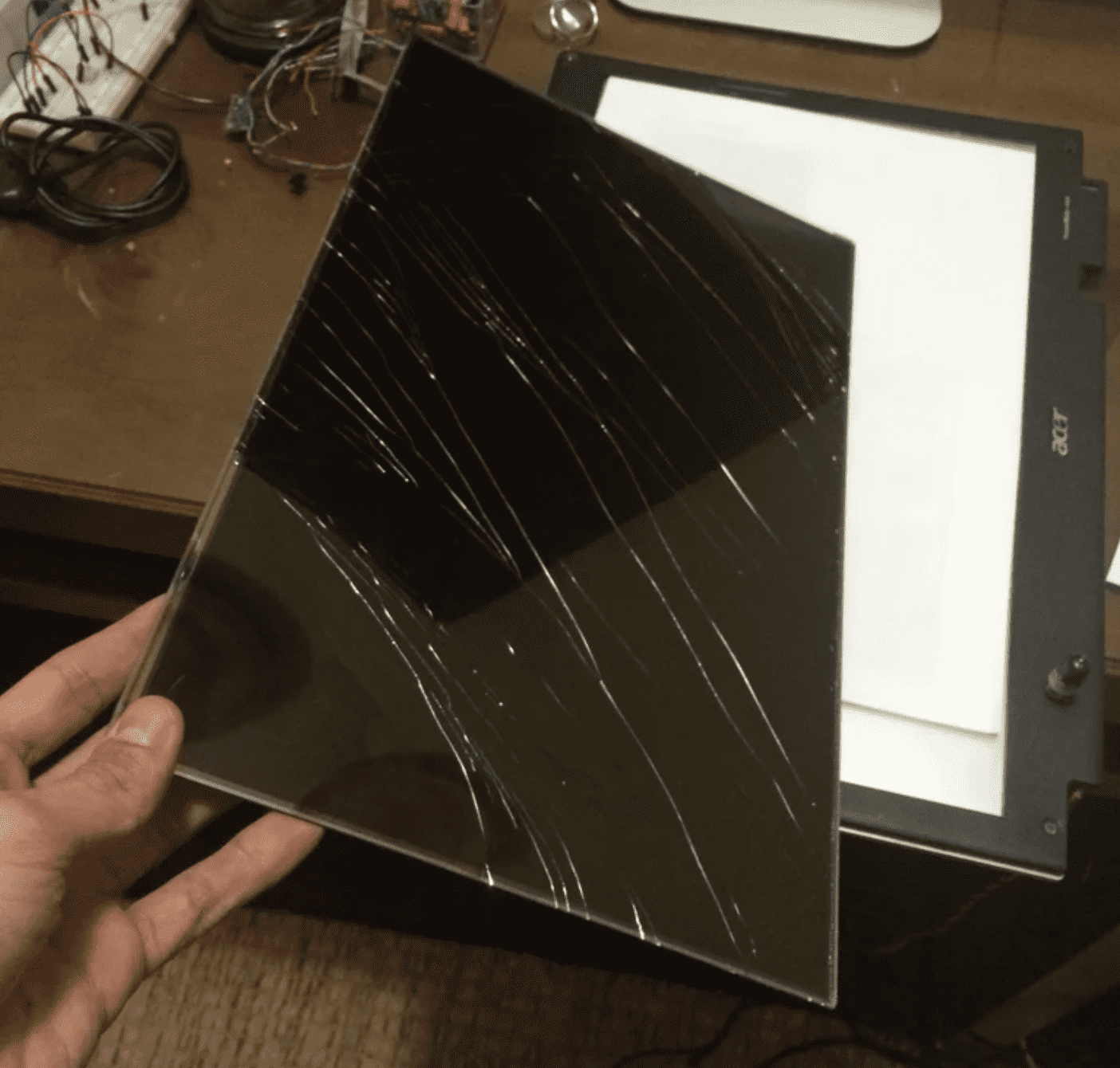
A friend donated me this old laptop, which had a broken LCD. The laptop was old but it worked just fine. I had no intention to spend money to get it repaired, it just would not worth the money. Instead I just removed the screen from the body of the laptop and used the laptop as a HTPC connected to a TV.
Then the screen part was pretty much useless, I could have just trashed it, but I just kept it, just in case I could do something with it. Then I had this idea that I could turn it into something useful.
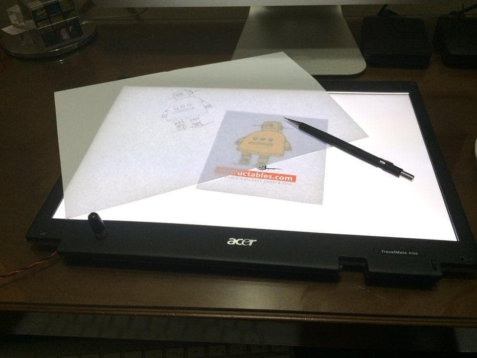
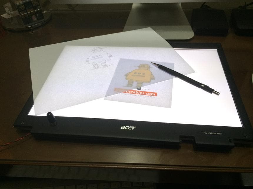
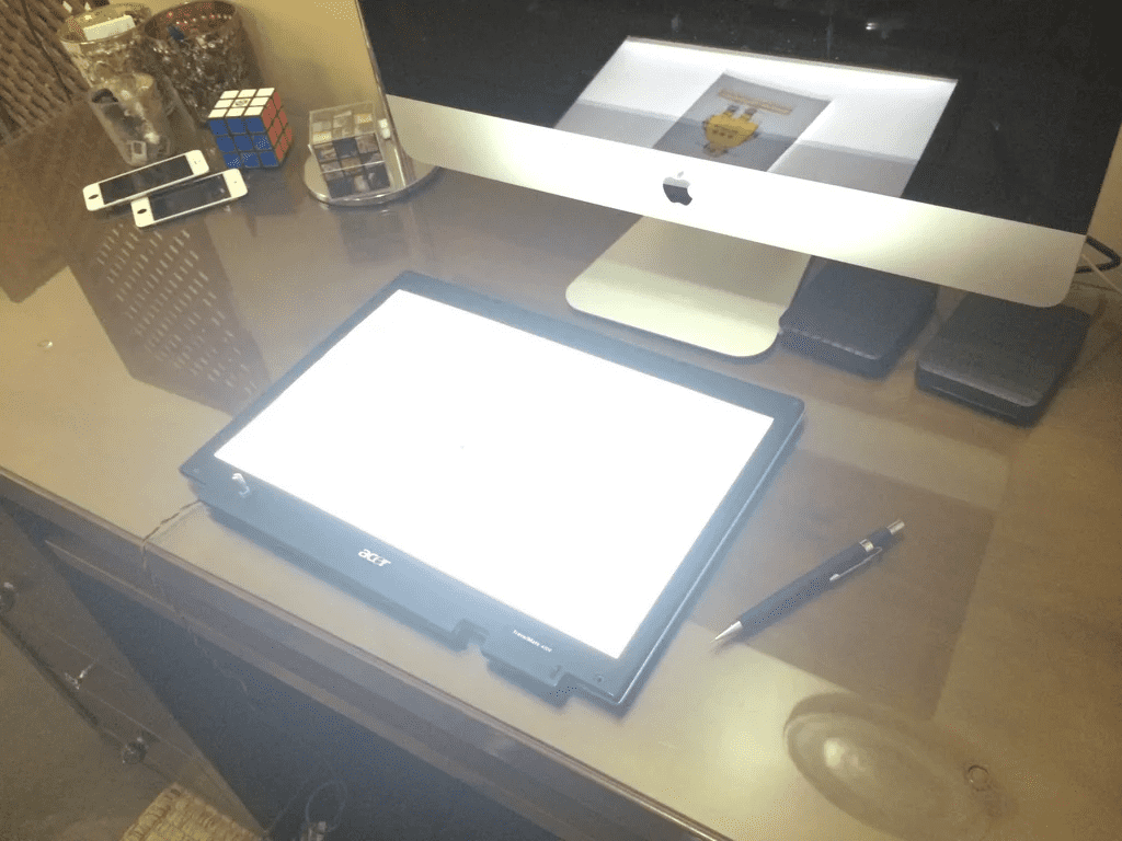
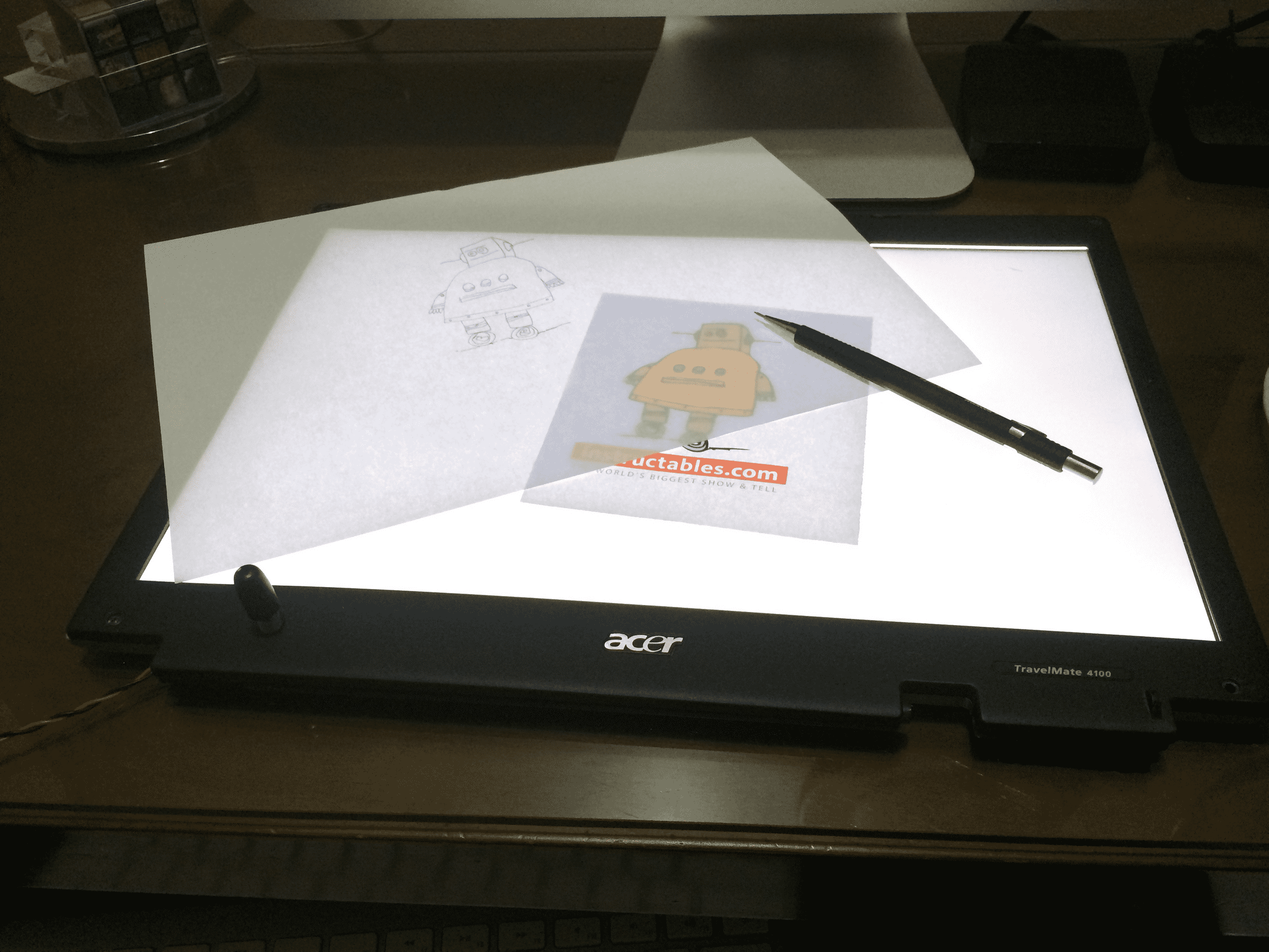
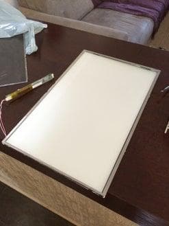
It turned out that it is very easy, and very useful if you're into drawing. It is a light board/table for drawing, it is very cheap and portable, you can easily carry on your backpack with your books.
A friend donated me this old laptop, which had a broken LCD. The laptop was old but it worked just fine. I had no intention to spend money to get it repaired, it just would not worth the money. Instead I just removed the screen from the body of the laptop and used the laptop as a HTPC connected to a TV.
Then the screen part was pretty much useless, I could have just trashed it, but I just kept it, just in case I could do something with it. Then I had this idea that I could turn it into something useful.
It turned out that it is very easy, and very useful if you're into drawing. It is a light board/table for drawing, it is very cheap and portable, you can easily carry on your backpack with your books.
Step 1:
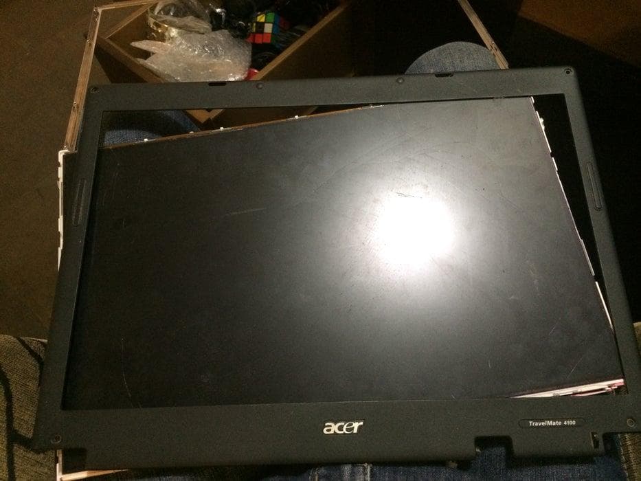
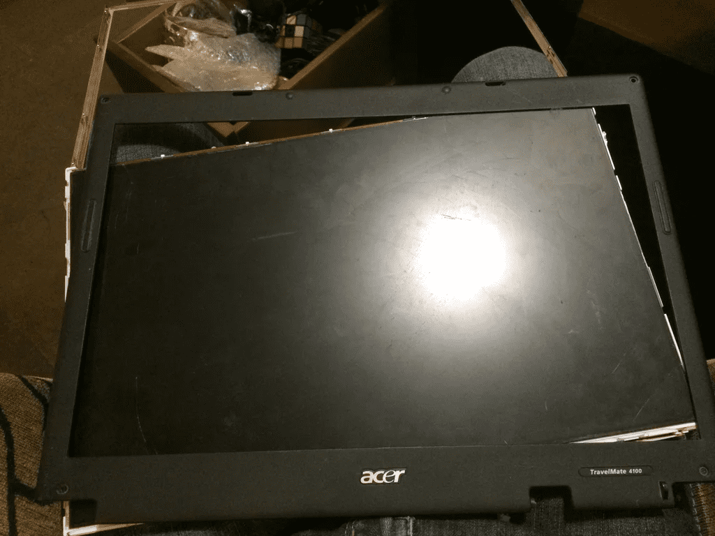
Take the old laptop apart, and separate the screen completely off the body of the computer.
Step 2:
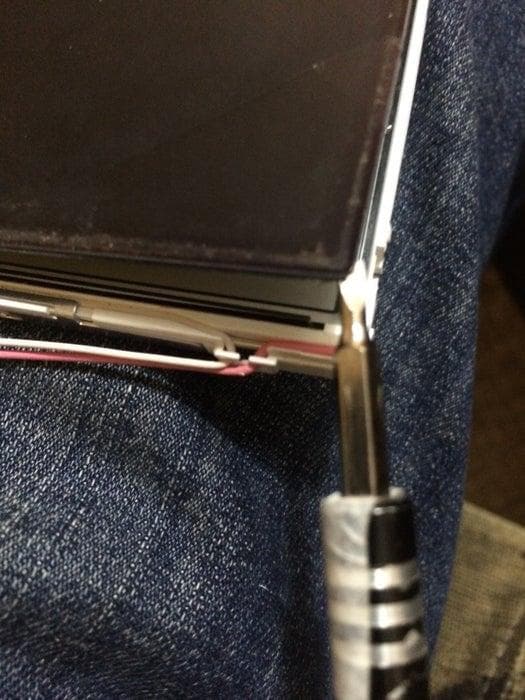
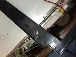
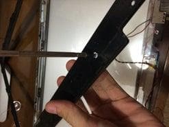
Remove the LCD itself from the plastic housing, then start to pry open the metal bezel. There are some screws you need to remove and then some retaining clips.
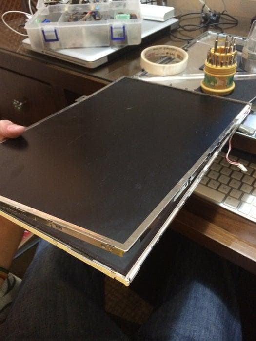
Step 3:
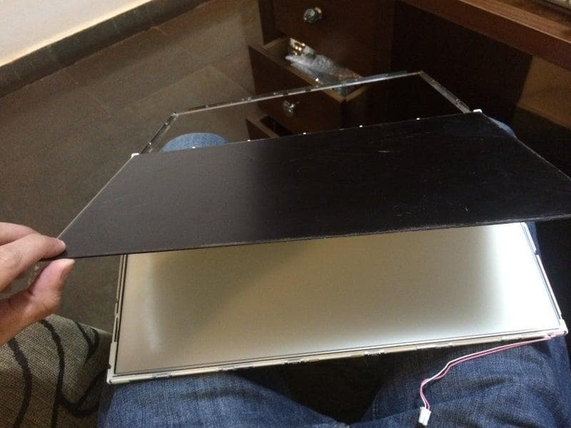
After removing the metal bezel, you can remove the broken LCD from the rest of the LCD assembly.
Step 4:
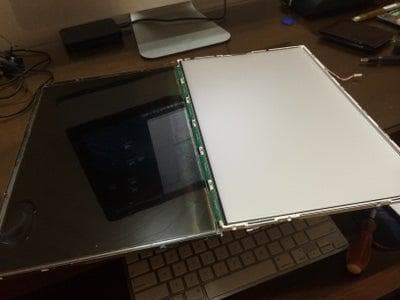

The driver board will come off with the LCD.
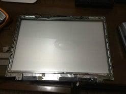
You will be left with the backlight, try to not touch the layers.
The backlight is made of a lamp CCFL in this one or LED strip, reflective sheet, a guiding glass, some fresnel films, and diffuser films. They have a very specific order, orientation and side. Just keep then as is, or it will be very hard to get then in the correct way later.
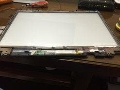
Step 5:
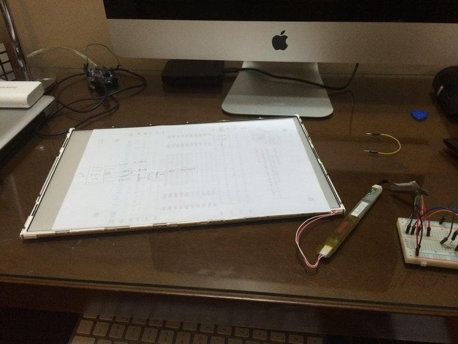
Now we will work with the backlight circuit.
This screen have a CCFL lamp, this type of lamp requires a Inverter board to light up. This board is attached on the bottom of the screen, you can just use this original board.
If you have a more modern screen with led backlighting, It will not have a inverter board, you easily make then work as well. You will need to build a led driver circuit, and if you want then to be dimmable a PWM circuit will be required.
Step 6: Inverter Board Pinout
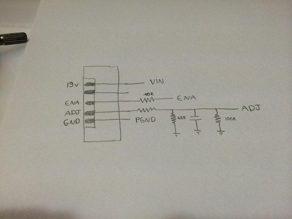
I reversed engineered the inverter board to find the correct pinout.
What I did was, the board have a controller IC, I looked for the data sheet of that IC and found its pinout description, so I traced where the pins of the connector would go to which pin on the IC.
Step 7: More on R.E.
Hope this can get you some hints on how to reverse engineer part of the circuit in order to find its pinout, because every board is a little bit different.
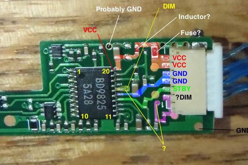
This is a picture of a inverter board a user asked on the comments.
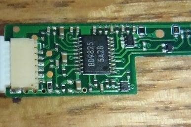
He sent a picture of his board. The main device is this BD9825, search for it on google followed by the keyword "datasheet", what you're looking for it is a PDF document containing all the information about this chip.
http://pdf1.alldatasheet.com/datasheet-pdf/view/13...
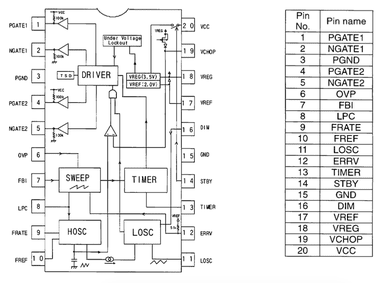
The data sheet contains a description of each pin. Look at your board, the chip should contain a marking on one of the 4 corners a little dot indented, or a U groove in one side. This indicates pin 1. To make things easier rotate your board and orient this on your top left. Then count the pins counter-clock wise.
   ___  __
1-| * \/  |-6
2-|       |-5  This is how you would orient and count pins on a chip.
3-|_______|-4
The easiest is always to find what is the GND (Ground) pin. The data chip specify GND as pin 15, count the pins and find out which pin is the 15, then follow the trace coming out this pin until it reaches one of the pins on the connector on the side, then now you know what this pin is GND. If it goes to a via follow it on the other side, if it goes underneath something you can't see were it goes, the make you best guess were it pokes out, the use a multimeter to check continuity to know if your assumption was correct.
I did basically the same with the other pins.
The GND should be very straight forward from the pin to the connector, using large traces, or ground planes, and maybe attached to multiple pins.
VCC should be a thicker trace as well, should contain one or more bypass capacitors (beige retangular devices with 2 pads) across VCC and GND, may have a in series inductor (looks like a black rectangle probably without a number on it, you multimeter should read near zero ohms if it is a inductor), and may contain a fuse in series (there are black, white, or green fuses, but should read 0 ohms).
The other Enable/Standby Adjust/Dim pins should be thinner traces coming out of the IC and will probably contain a resistor/capacitor network, to make it simpler just follow the board traces, if the traces ends on a component, continue following the trace after the resistors (black ones, with 3 digits on it) not the capacitors (yellowish ones), the capacitors will probably end to ground.
This board was different than mine, it has a STBY instead of ENABLE, and DIM instead of ADJ, but this shouldn't make much difference apart from labeling. But the data sheet is not very clear about what the levels are for DIM.
The VCC voltage should be the same as the stock power supply of the laptop it came from.
Step 8: Aditional Circuit
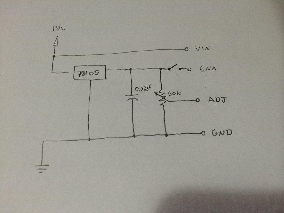
To power the inverter board it require 19v, and 5v logic.
So I came up with simplest circuit in order to make it work.
A low power 5volts linear regulator, to provide logic HIGH to the enable pin and a variable potentiometer to provide the analog input to the dimmer IC.
Step 9:
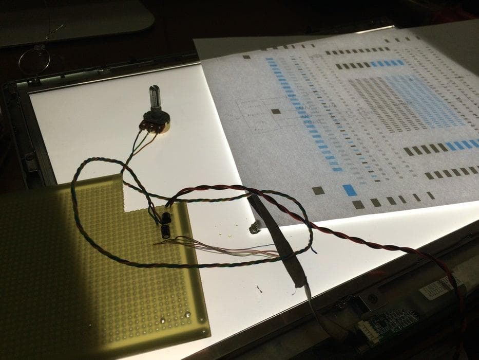
Solder the circuit to a perf board, and test if it work.
Step 10: Fitting Everything
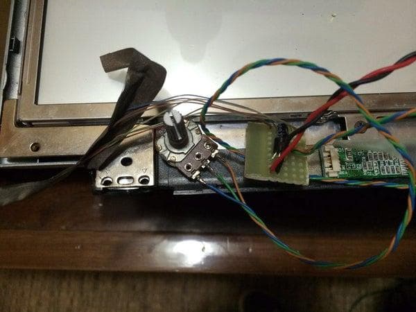
After cutting the perf board, make sure it will fit inside the case.
Make sure it is not touching any metal, and hot glue everything.
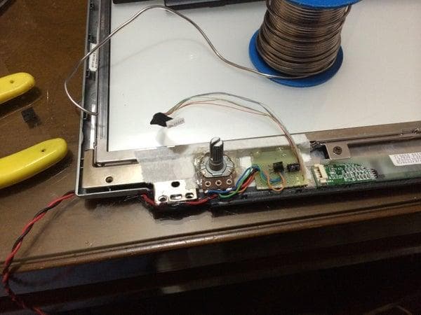
Step 11:
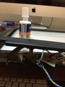
You can mark the tip of the potentiometer with white-out, and touch the bezel to know were to cut a whole.
I used a screwdriver to dig a whole in the plastic and enlarge it with a knife. If you find hard to make a whole in harder plastics, just heat up a screwdriver with a fire, and melt a whole.
Step 12: Glass
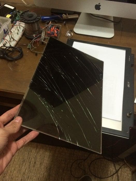
I took the broken LCD to a Glass Store and bought a glass sheet of the same size. It was a bit thicker though about 3mm, but I could fit it inside the original lcd assembly.
It was very cheap, about $ 2.50.
Step 13: Feet
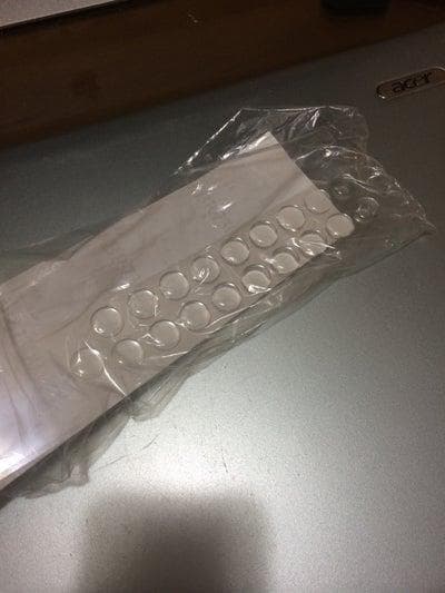
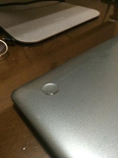
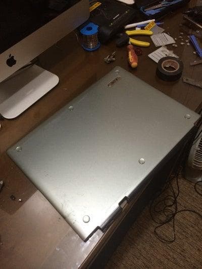
Add some silicon/rubber feet on the other side. You don't want it sliding around.
Step 14: Final Result
Here is the final result.