Turn an old car radio into a Hi-Fi Audio Amplifier
Posted originally on Instructables Published May 22nd, 2015

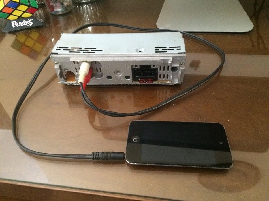
[https://www.instructables.com/Recycling-old-car-radio-into-a-audio-amplifier/](https://www.instructables.com/Recycling-old-car-radio-into-a-audio-amplifier/)I got this old cd player that was pretty much waste, because It had its front panel lost. Even if it worked I don't have any physical media nor I wanted to listen to radio. But I knew that I could use the amplifier part and use it to drive some speakers, and then connect it to any audio source that I wanted like an iPod, phone, TV, etc.
It then worked very well, and the 4-channels came in handy, so I could connect it to 2 speakers plus 2 larger woofers, to give some Bass! For that I modified 2 of the channels to only reproduce bass, using a very simple low-pass filter.
This made a great setup to replace the very bad speakers that I have on my cheap TV. Now I can enjoy netflix and video games with decent audio, with some bass response to it.
All of that, basically for free! It was going to the trash bin anyway, mother nature is thankful for that, so it's my wallet. :)
Most of the time and efforts goes in trying to figure out how it works, and what you need to do. Once you figured out, the modifications are very minimal, and straightforward. Just some traces broken and a few jumper links to make it work. The only additional part is a 12v wall wart adapter that can provide a few amps, that can be savaged easily from old stuff.
It's certainly doable with any radio, but some will be more challenging then others. Since every model will be different, you will have to figure out by yourself like I did.
Step 1: How to Take Pictures
You don't need anything special, just a regular camera with non-fixed focus this is very important. And good lighting.
The camera used to take this pictures was an iPhone 5S camera.
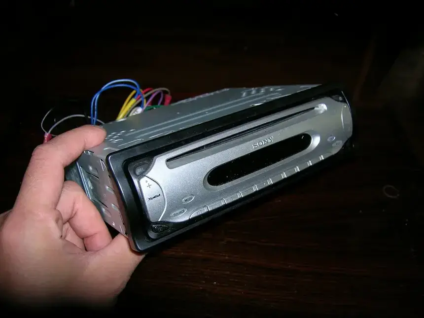
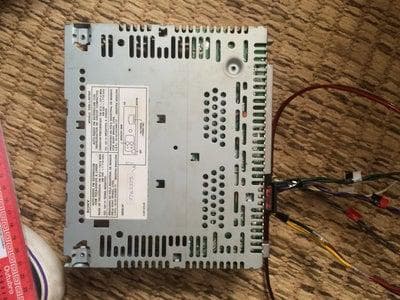
Very important tip, take your pictures outside, you can see it makes a huge difference (first picture indoor with regular CCFL lighting, second picture outdoors). Try taking multiple shots at different positions relative to the sun to avoid shadows and glares, with different exposure and focus, and distance. Then pick the best one.
Picture taken with indoor lighting

Picture taken outside

Step 2: Getting Details to Start R.E.


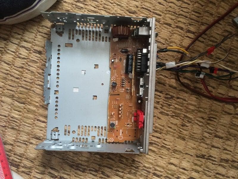
We need as much as information as possible about the heart of the amp.
In this case there's a big 24-pin device attached on the back heatsink, that's a dead giveaway that it is a power device.
In some cases, you will find discrete amplifiers, and those can be some sort of transistor array or H-bridge. But in this case I'm looking for a Class AB amplifier of some sort, because at first glance I can't see any output filtering stage, not a single inductor or big electrolytic capacitor (apart from one in the 12v supply) that would appear in a Class D amplifier.
Thankfully there's a part number that we can search for a data sheet. TA8272H and I found out that this is a full audio amplifier in a chip, it is a linear bipolar amp or like I guessed a Class-AB Amplifier. They are not impressively power efficient (they waste power as heat), but they have inherently less noise and distortion when compared to more modern Class-D amplifiers (which can output a lot of power with very little waste heat, but usually comes at a cost in quality, they usually have higher distortion and lower fidelity overall). So this makes it the ideal amp for driving high quality speakers that are not super huge in power, like passive monitors speakers or book shelve speakers, which is what I’m going to use it for. Budget studio quality (Did I mention they have incredible flat response as well?!)
Step 3: Reverse Engineering!
Please view the Original Size pictures:
I explain in more details how I align images here in this tutorial: How can I reverse engineer a simple through-hole board?
Based on the datasheet, I start to enumerate the known pins and traces, on layers on top of the image, then I will follow traces, and sometimes make assumptions to were it goes, then check continuity using a multimeter to make sure that I guessed it right.
I highlighted every trace that was important and required to get the amp working, from its power supply, inputs and outputs, and control pins. I back traced the speaker outputs from the rear panel through the board in magenta. Ground is always easy, I highlighted ground in Blue, (everything in a car is that is attached to the chassis is ground, so you can test continuity easily to know it it's ground). In Red, I highlighted the 12v line that comes from the yellow wire that comes from the car battery. Each of the 4 audio inputs is highlighted in a distinct color.
Everything else was useless. So I broke some traces that powered the other parts of the circuit that I won't need. So I just needed to add a jumper link on the stand-by pin of the IC, that before it was only powered by the micro controller, when the radio was on.
I Injected signals direct to the input pins, and voilá. audio came out of the speakers.
Since it had a couple of RCAs outputs on the back, I just redirected the audio from the audio-out connectors to feed audio to the amp.


Step 4: Shrinking the Board
Most of the stuff of the board was not being used. Since I had every important trace drawn on the screen, I found that I could strip 2/3 out of the board much trouble. Again after breaking it apart just cut traces to make sure I had no shorts.


Step 5: Crossover
Since this is a 4-channels amplifier, and I had only 2 inputs connected, I wanted to make a kind of subwoofer using 2 smaller speakers and 2 woofers.
So I made 2 low-pass channels that will reproduce most of the bass, and 2 full range channels but I added a 12dB attenuator, to enhance the low-pass channels.
The low pass filter consist of a simple RC filter that will give a roll out of -3dB per octave with the cut off frequency of fc = 79.5774715459[Hz]. Determined by a 10K resistor with 2 100nF ceramic capacitors in parallel.
And on the full range I added a voltage divider of a 10K-2K to give me some attenuation, to make the bass more pronounced than the full ranges.
http://hyperphysics.phy-astr.gsu.edu/hbase/electri...
http://sim.okawa-denshi.jp/en/CRtool.php


Step 6: Volume
I don't have a volume control, but that's not a problem, we can just adjust the volume from our source, like an iPod, TV, etc. Or if you want just wire a stereo potentiometer in line with the input.
But you can go fancy, and add digital volume with remote control.
I explain how to make it in this Instructable: Remote Volume Control for old stereo amp
Step 7: Shrinking the Case


Step 8: Finishing

Step 9: Done!
Maybe next time we can incorporate a power on status led, stand-by switch, remote volume control and add blue tooth to the audio amp.