Remote Volume Control for Old Stereo Amp
💡 Posted originally on Instructables Published Dec 17th, 2014

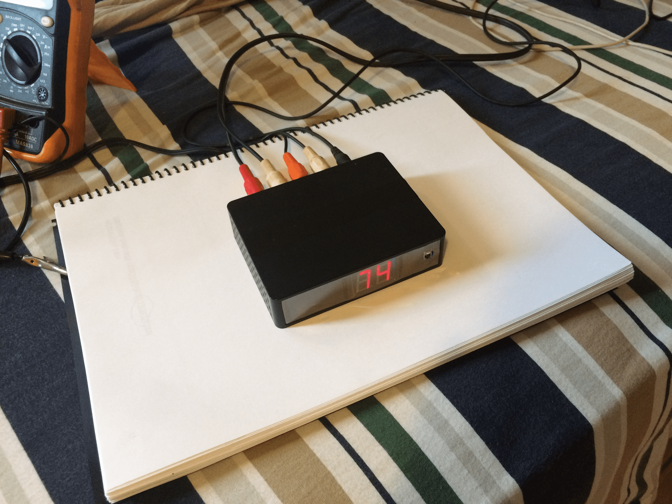
[https://www.instructables.com/Remote-Volume-Control-for-old-stereo-amp/](https://www.instructables.com/Remote-Volume-Control-for-old-stereo-amp/)I have an old Stereo Amp that I have on my living room. It works pretty good, but it is so old that It doesn't have a remote control, which makes it very annoying to use while sitting on the couch.
So I made this, a device that I could use my current TV remote to controle the volume and mute the stereo, It also works with this custom remote that I made for this project.
See: Make you own custom remote controle for your project
Step 1: Driving a 7 Segments Display
The video above, illustrate how I wrote a library that drives the 2 displays without a driver, just using the micro controller pins.
The video starts in a slow motion fashion so you can see every segment lit up individually, then it gets faster and faster, until it reaches normal speed and the digit 3 seems still. This technic is called multiplexing. Then it shows how two digits can be seem as fully lit up, but in reality only a single segment is lit at once. At normal speed it gives the impression that a 88 is being displayed. This technic is called multiplexing.
A multiplexed display has several advantages compared to a non-multiplexed display:
- fewer wires are needed, paralleling the displays except the common wire;
- simpler driving electronics can be used (single resistor per display, instead of one for each segment);
- both lead to reduced cost;
- reduced power consumption (since there's only a single segment powered at time);
The code for just the display multiplexing can be found here: https://github.com/victornpb/ledDisp
Or you can find the complete code for this project at the final steps.
Step 2: EVC
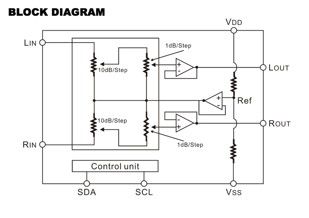
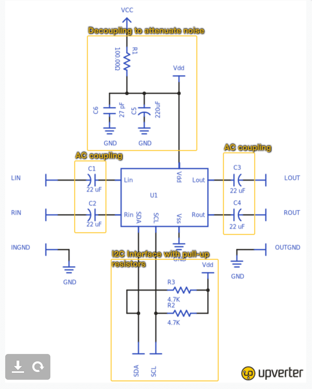
The electronic volume control I used the IC PT2257.
It is a digital potentiometer controlled by Serial I2C, It has 2 channels and has 10 attenuation steps of 1dB and 7 attenuation steps of 10dB cascaded. Meaning you can control the attenuation from 0dB to 79dB for every combination possible for each channel.
It is cheap, available on DIP package, and operate from 3 to 9v.
This data sheet provided all the needed information so I could write a library to drive it.
PT2257 Datasheet: http://www.princeton.com.tw/Portals/0/Product/PT2257.pdf
Step 3: Circuit Diagram
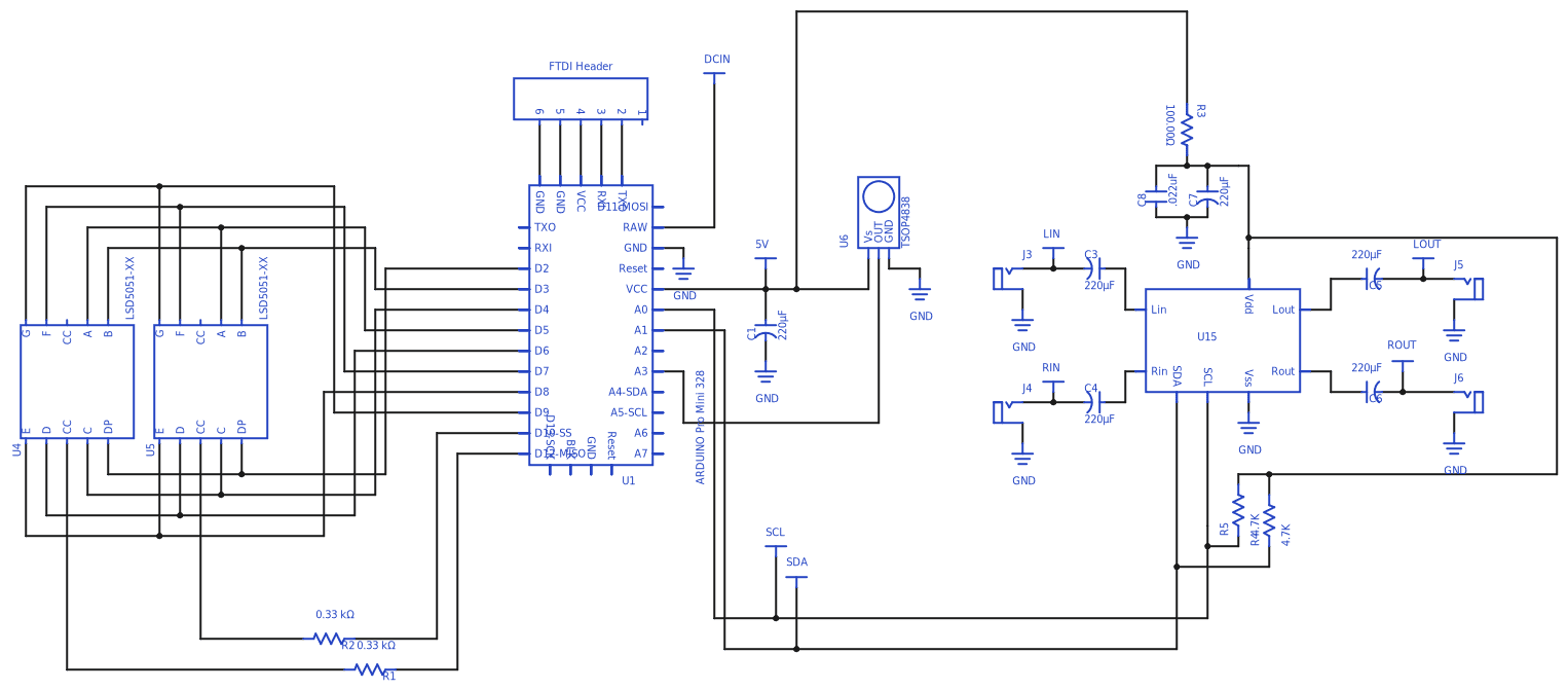
Full Schematic: https://upverter.com/victornpb/3c5e17ae8187633d/Yantar-VIII/
EVC Schematic: https://upverter.com/victornpb/1cfa0d918a888618/Digital-Volume-Control-PT2257/
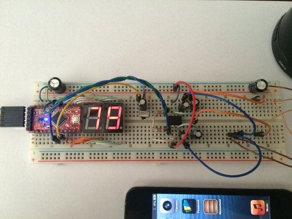
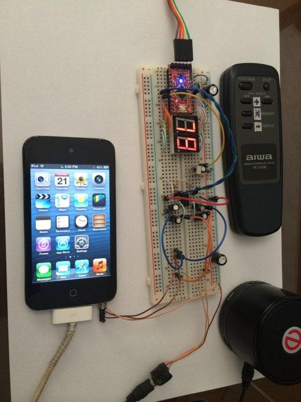
Step 4: Breadboarding
Testing if everything works together.
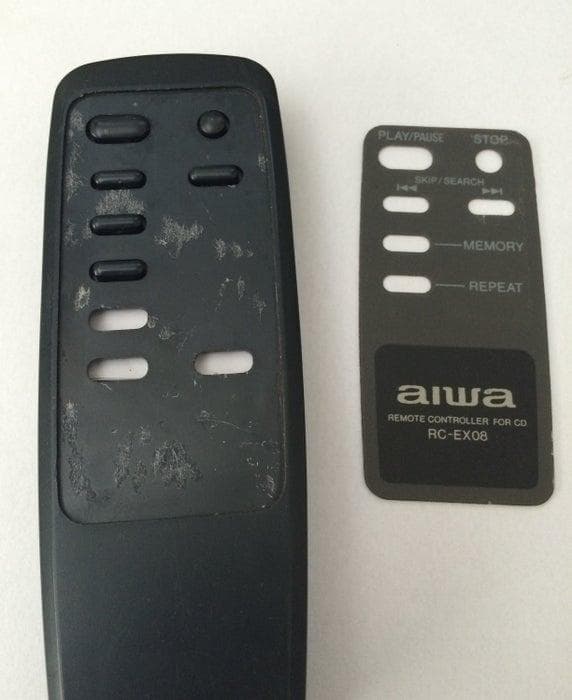
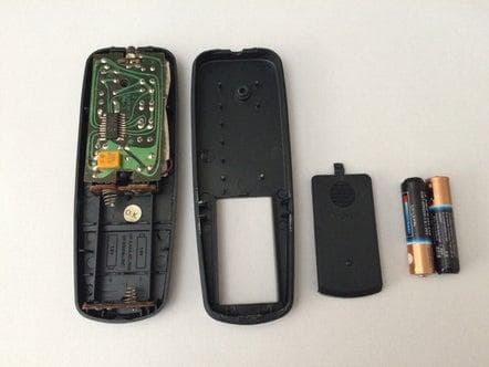
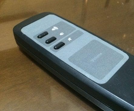
Step 5: Remote Control
If you want to know how I made the Remote Control,
I described it on details on a separated Instructable, check it out!
Make you own custom remote control for your project
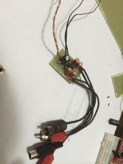
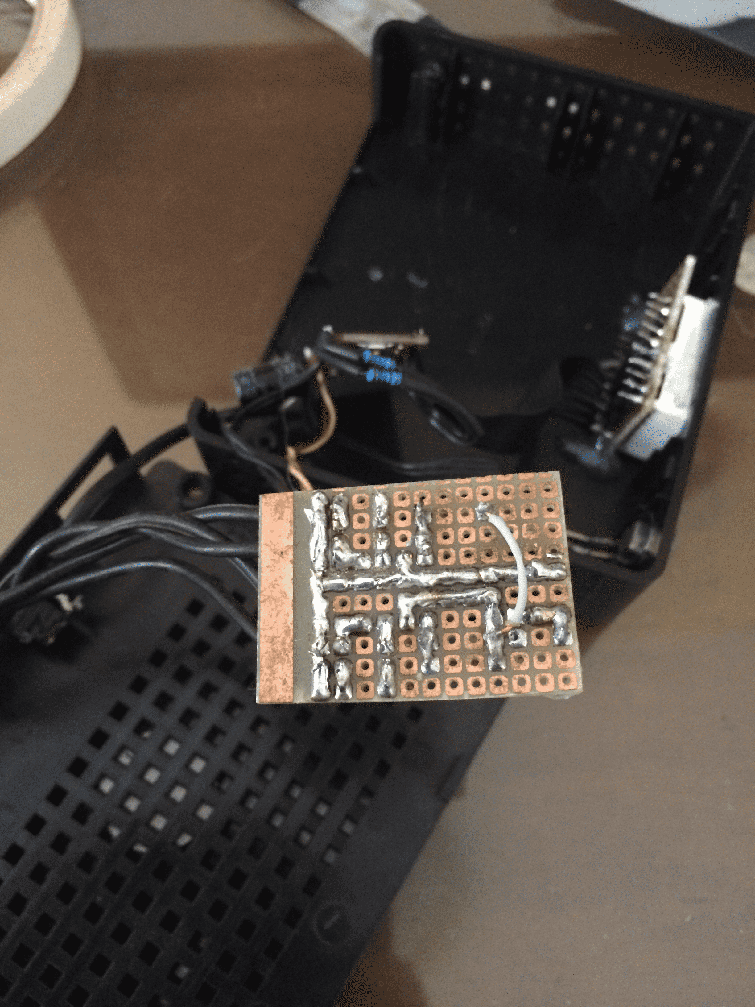
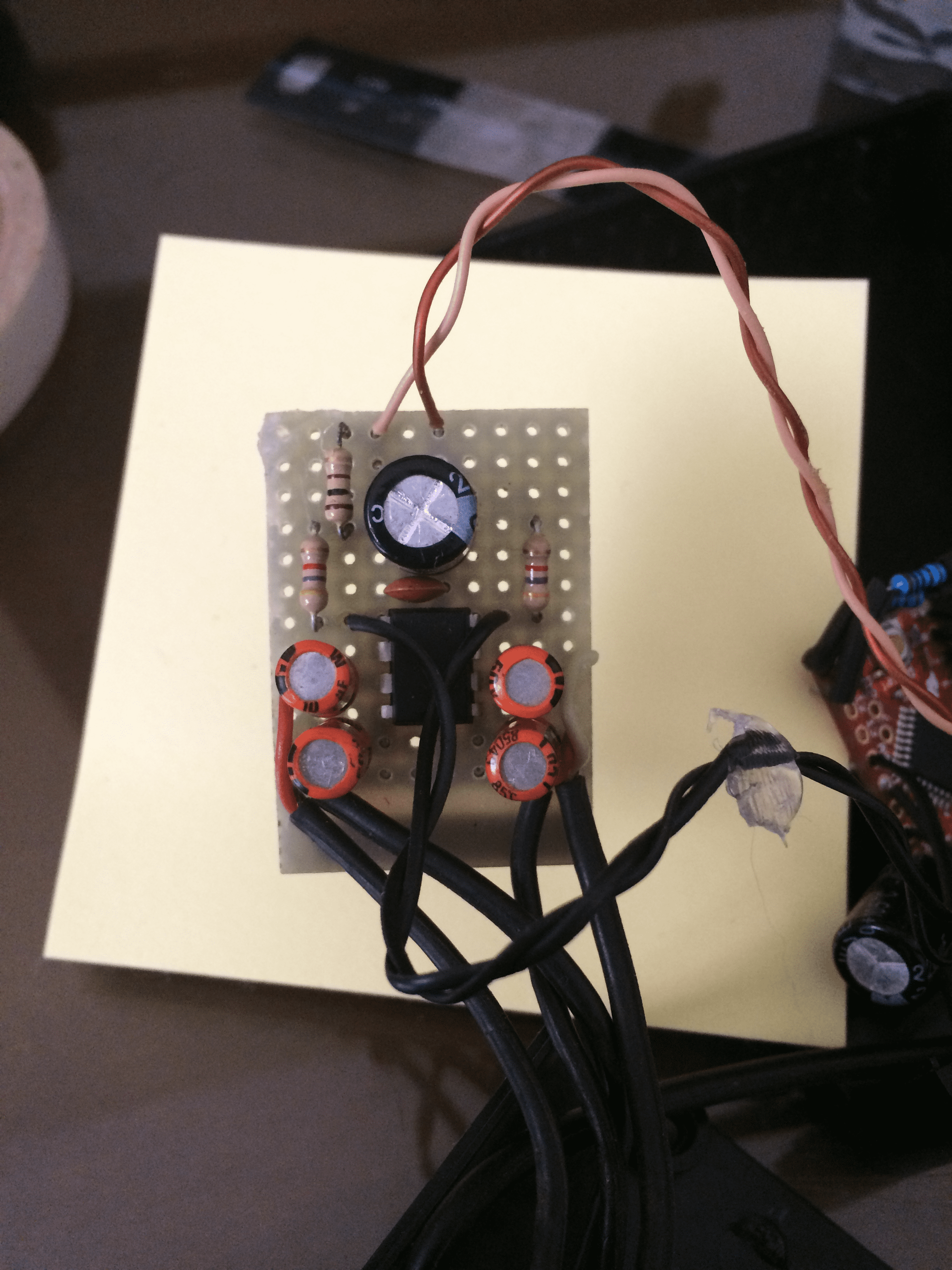
Step 6: EVC Board
I assembled the volume control circuit on a perf board.
I would make everything on a single board, but since this is audio path, I wanted to keep it simpler to isolate and shield if from the digital part if needed.
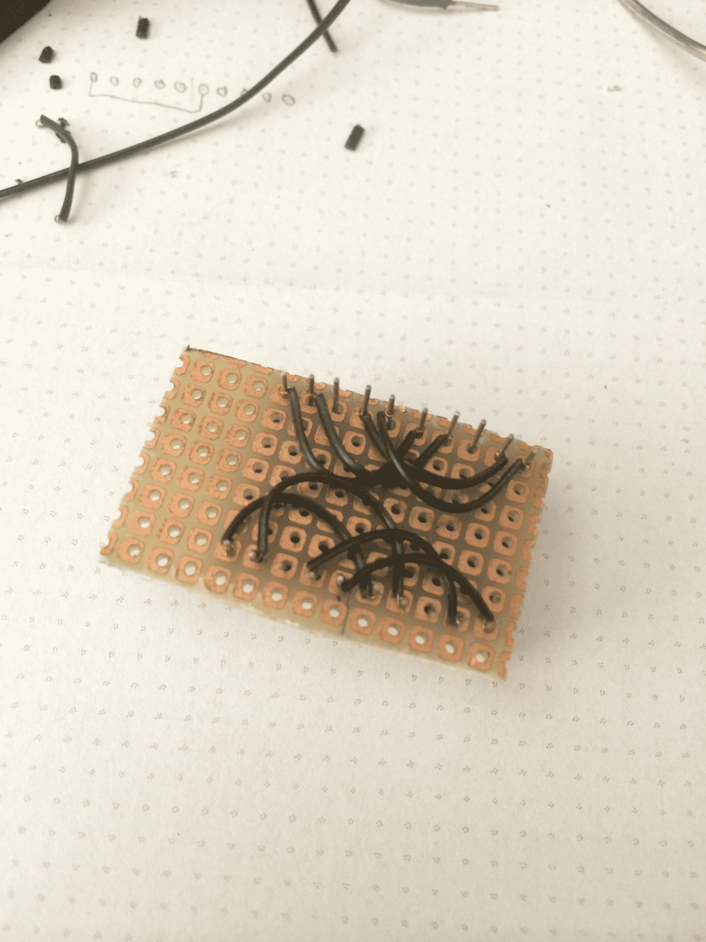
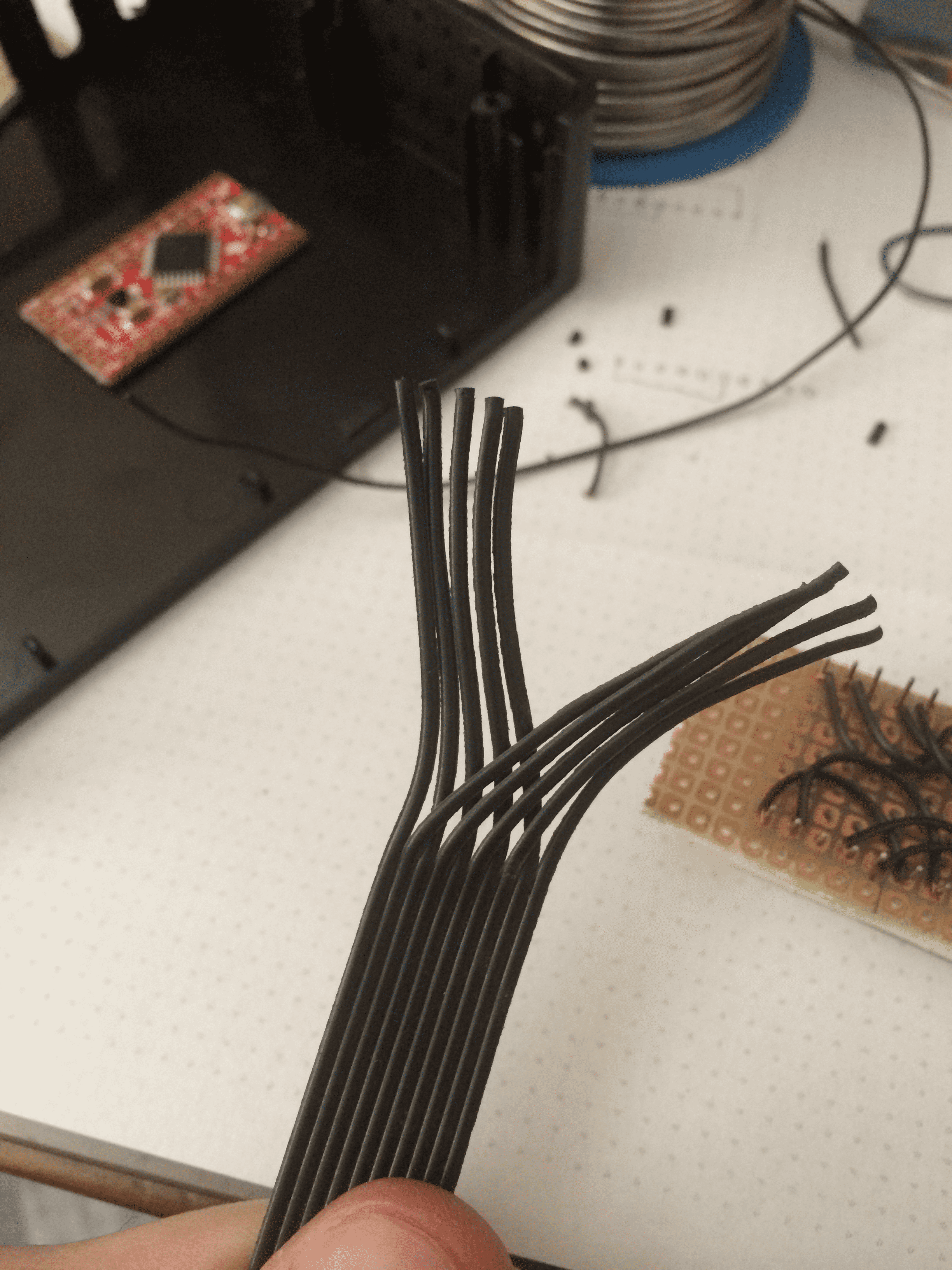
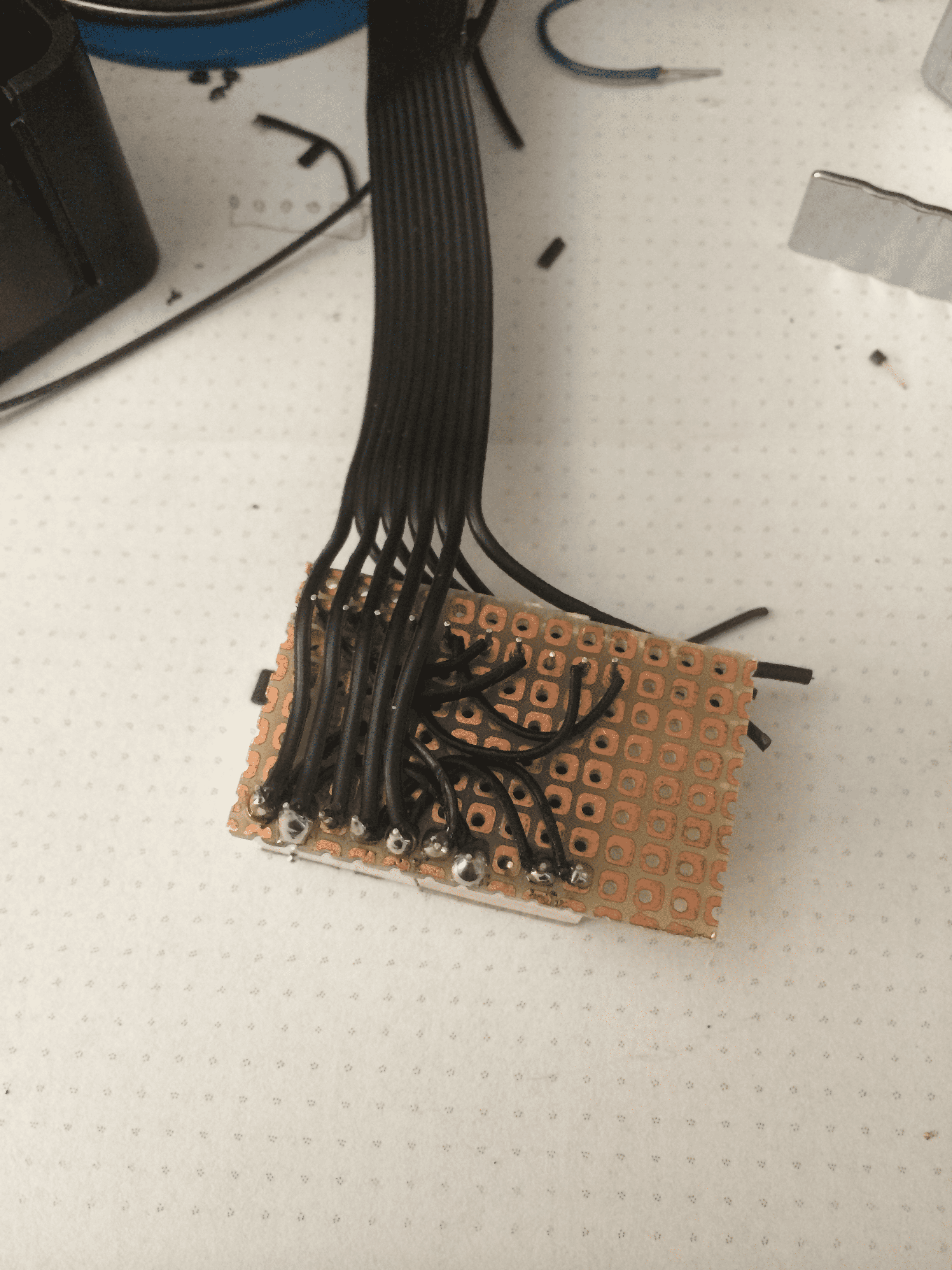
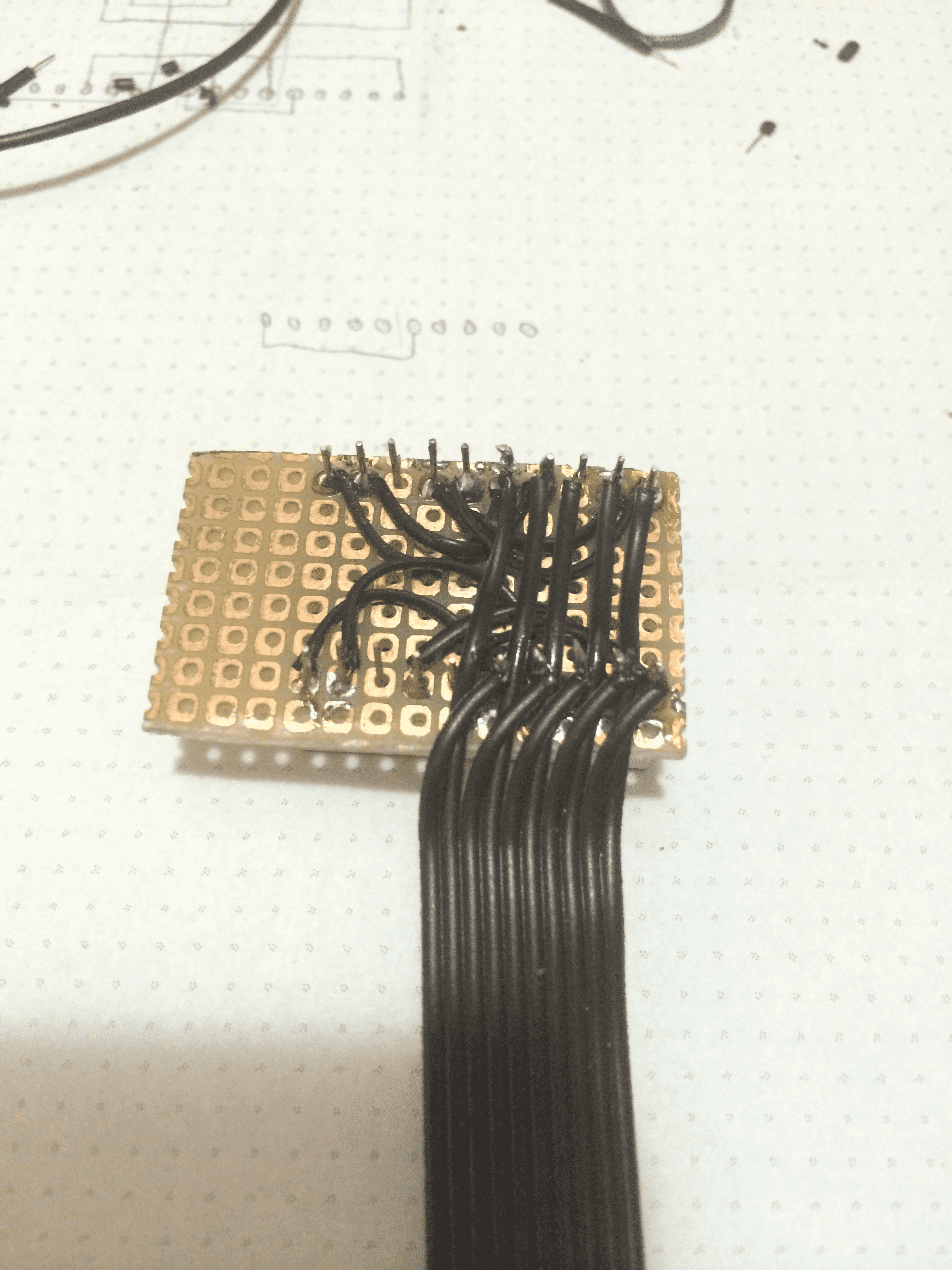
Step 7: Soldering the Displays and Attaching Ribbon Cables
Using a small piece of perfboard to hold the 7-segments displays together.
Solder it to the board, and solder every pin in parallel.
A old ribbon cable of an old IDE hard drive is very handy.
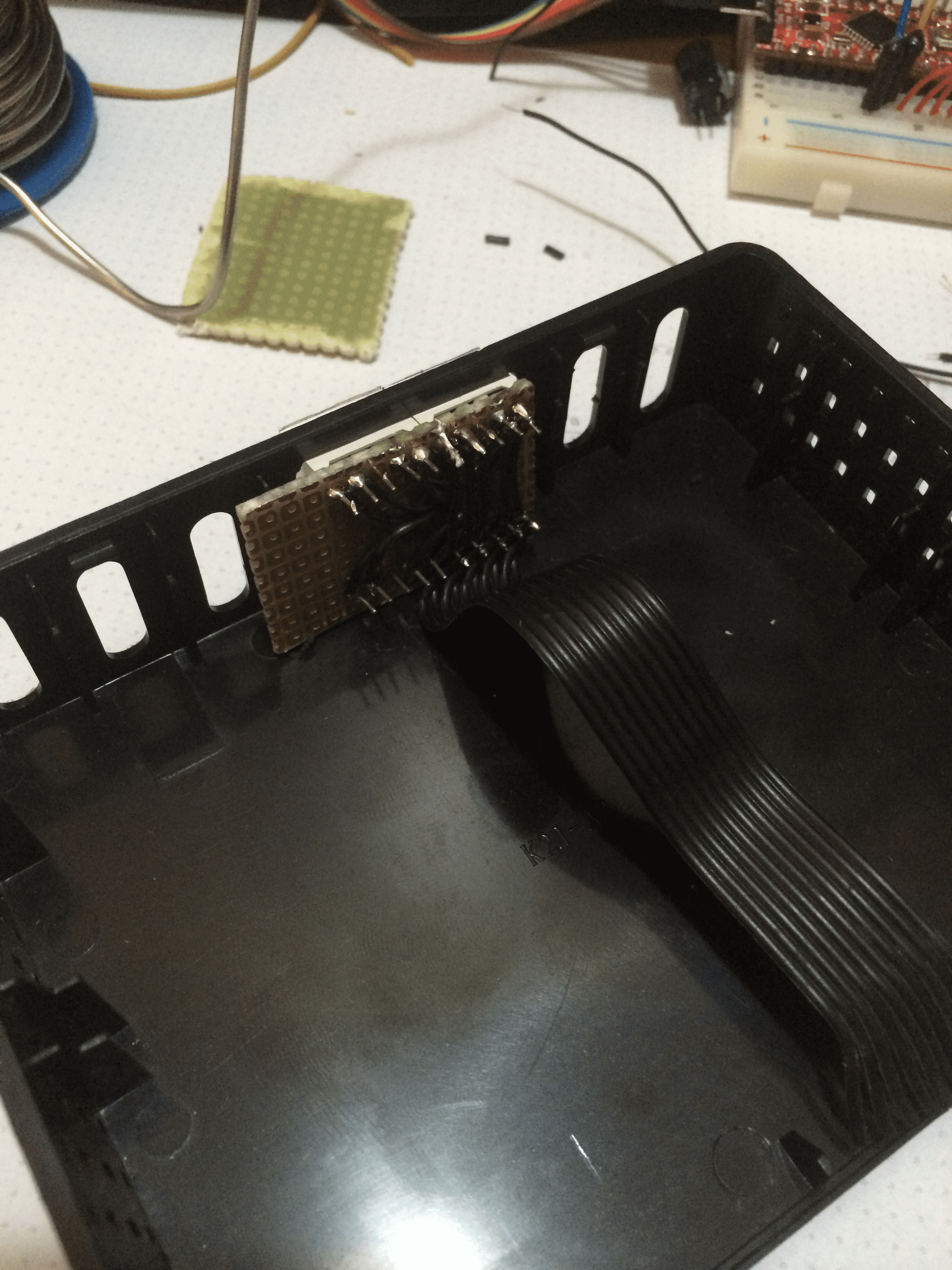
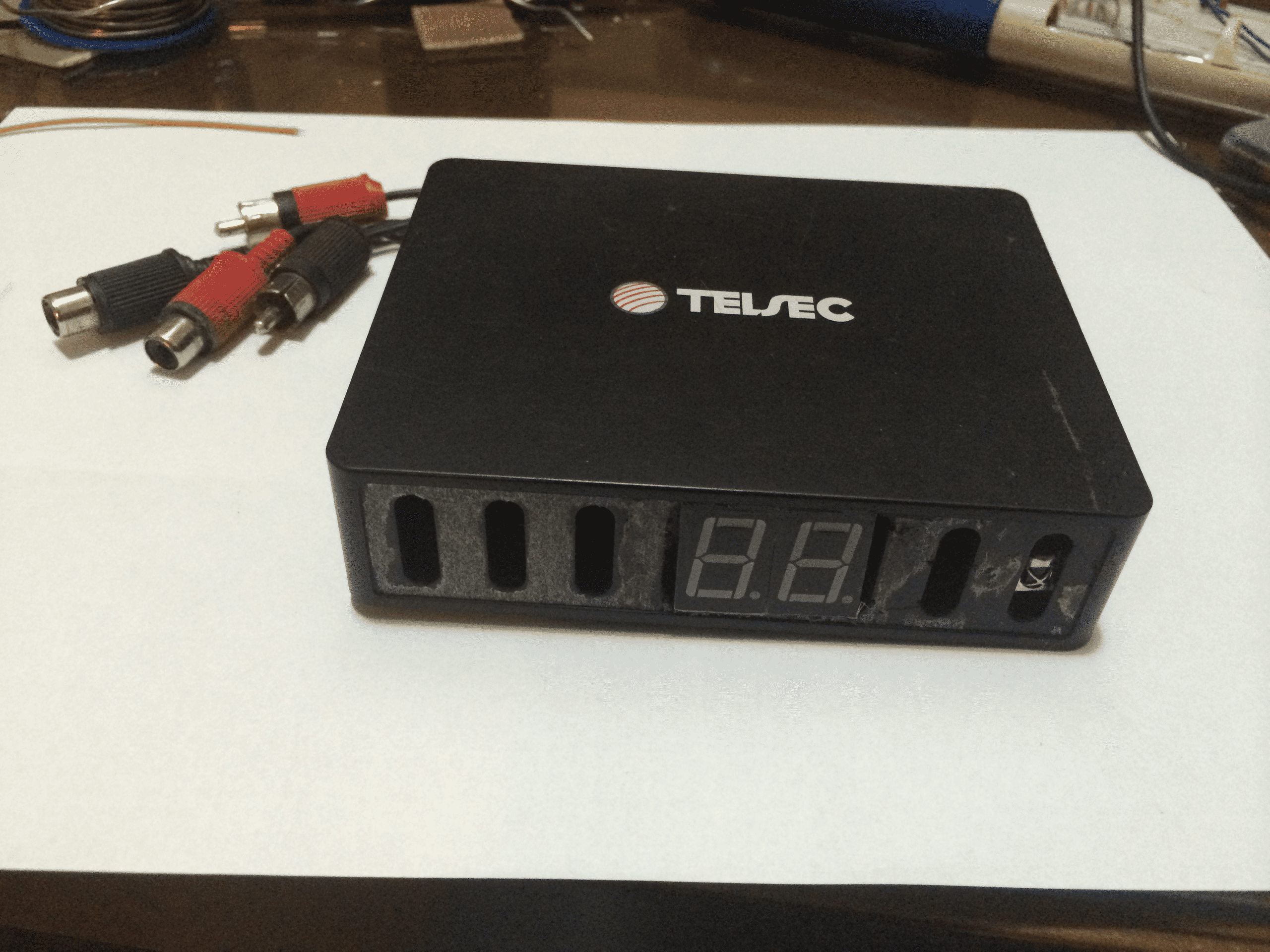
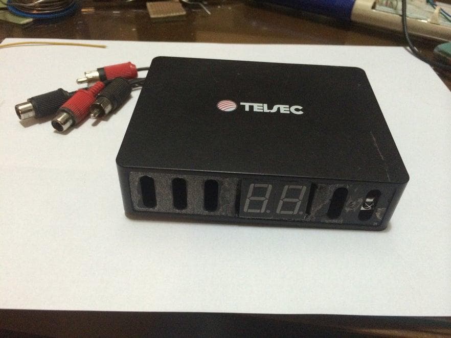
Step 8: Case
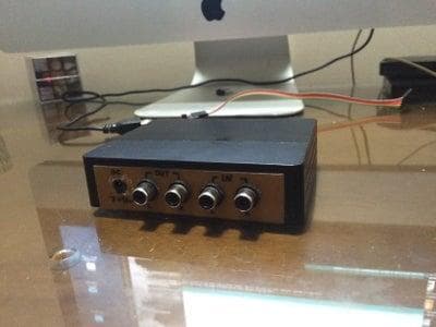
I used a case of an old ADSL modem I had, It got fried after a thunderstorm.
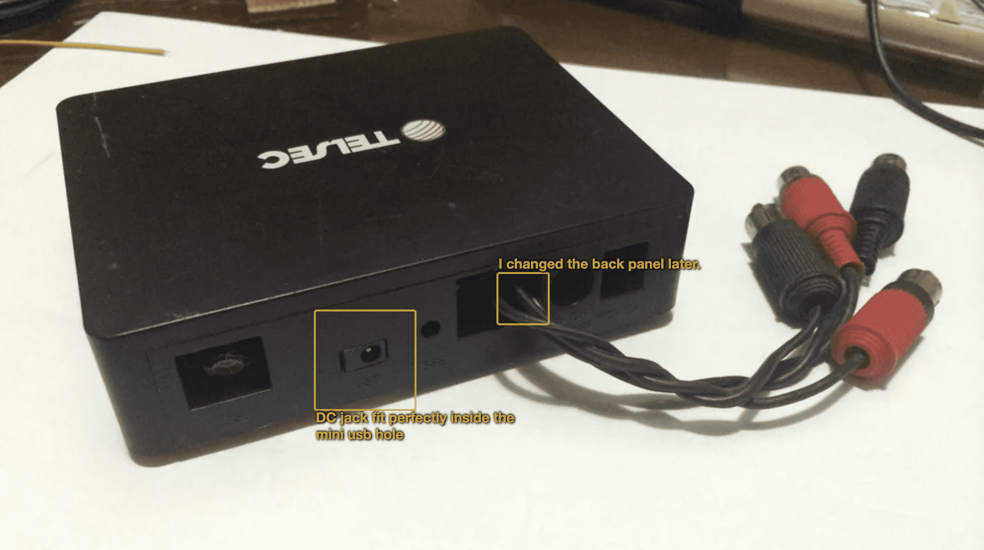
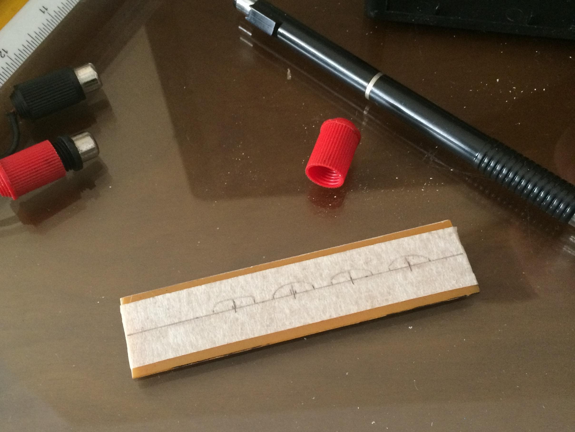
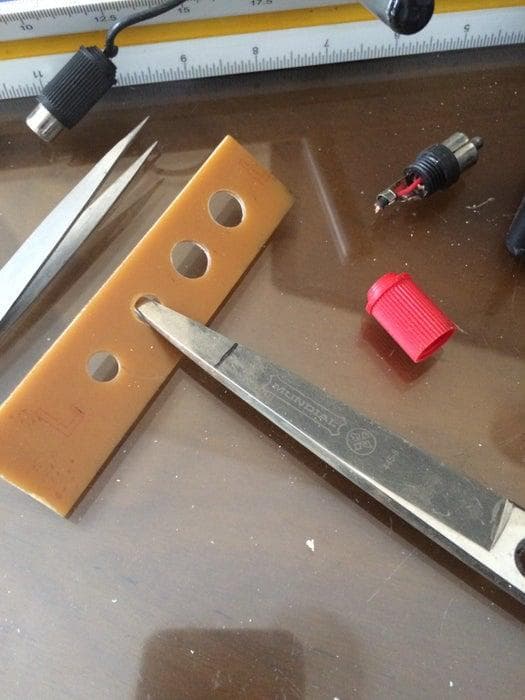
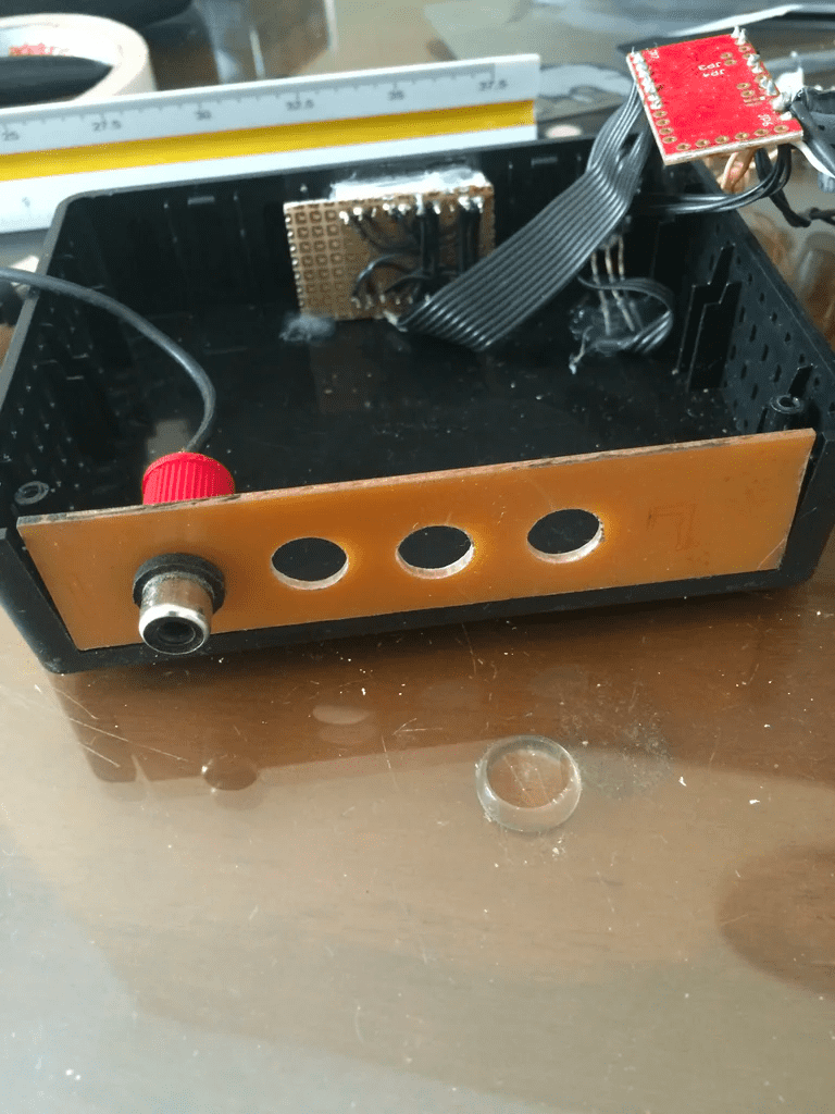
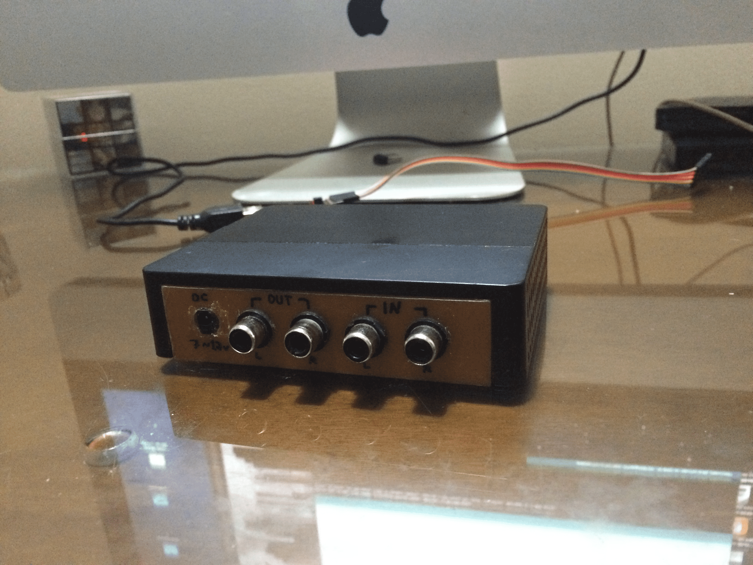
Step 9: Back Panel
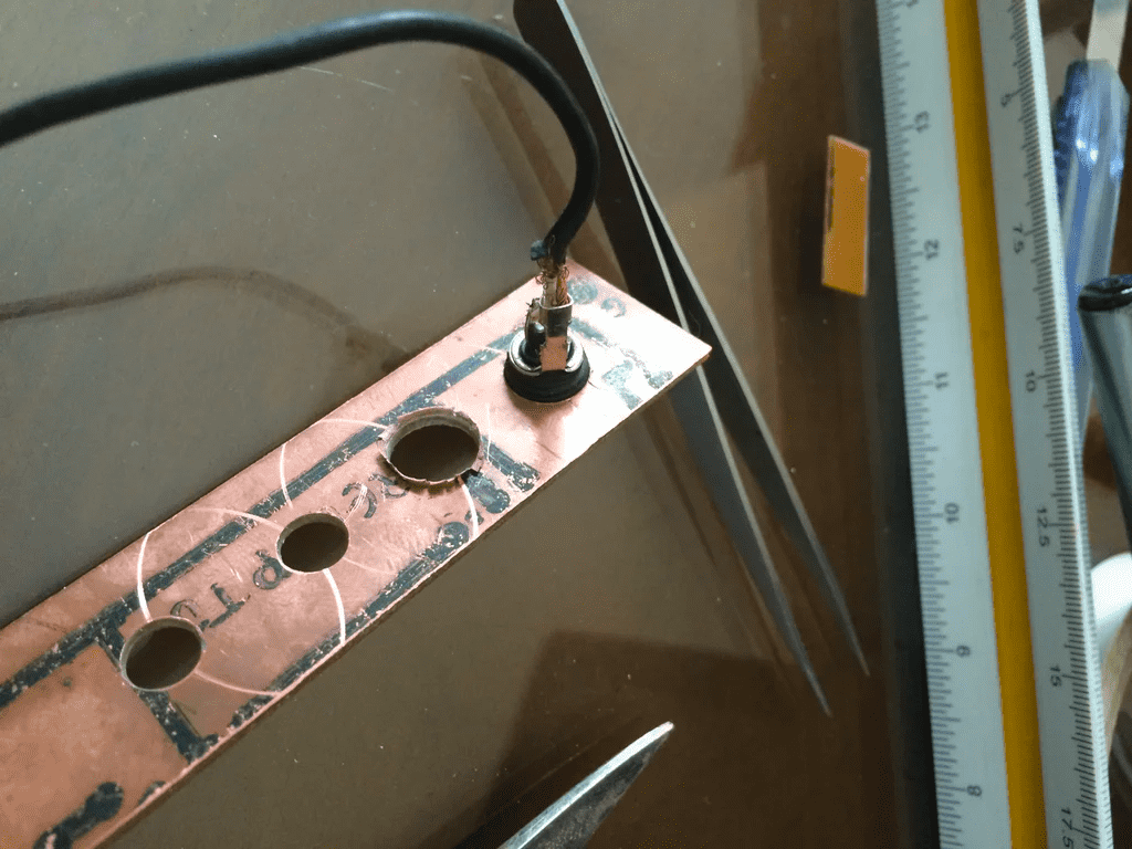
I snapped a piece of copper clad I had laying around, to the correct size.
Measured it, and made marks to where to drill holes.
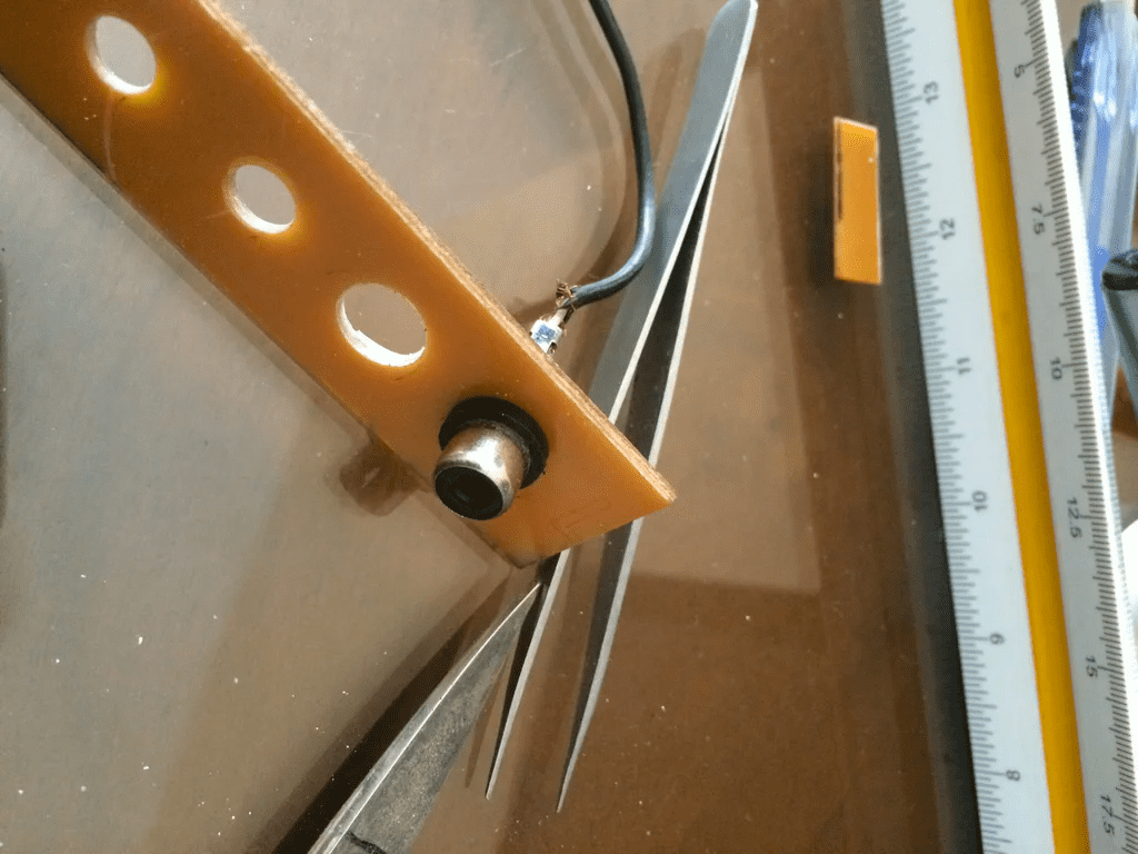
Step 10: Drilling Holes and Expanding Then
I used a drill to make holes and the enlarged the radius until the connectors could fit.
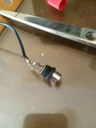
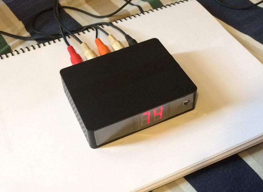
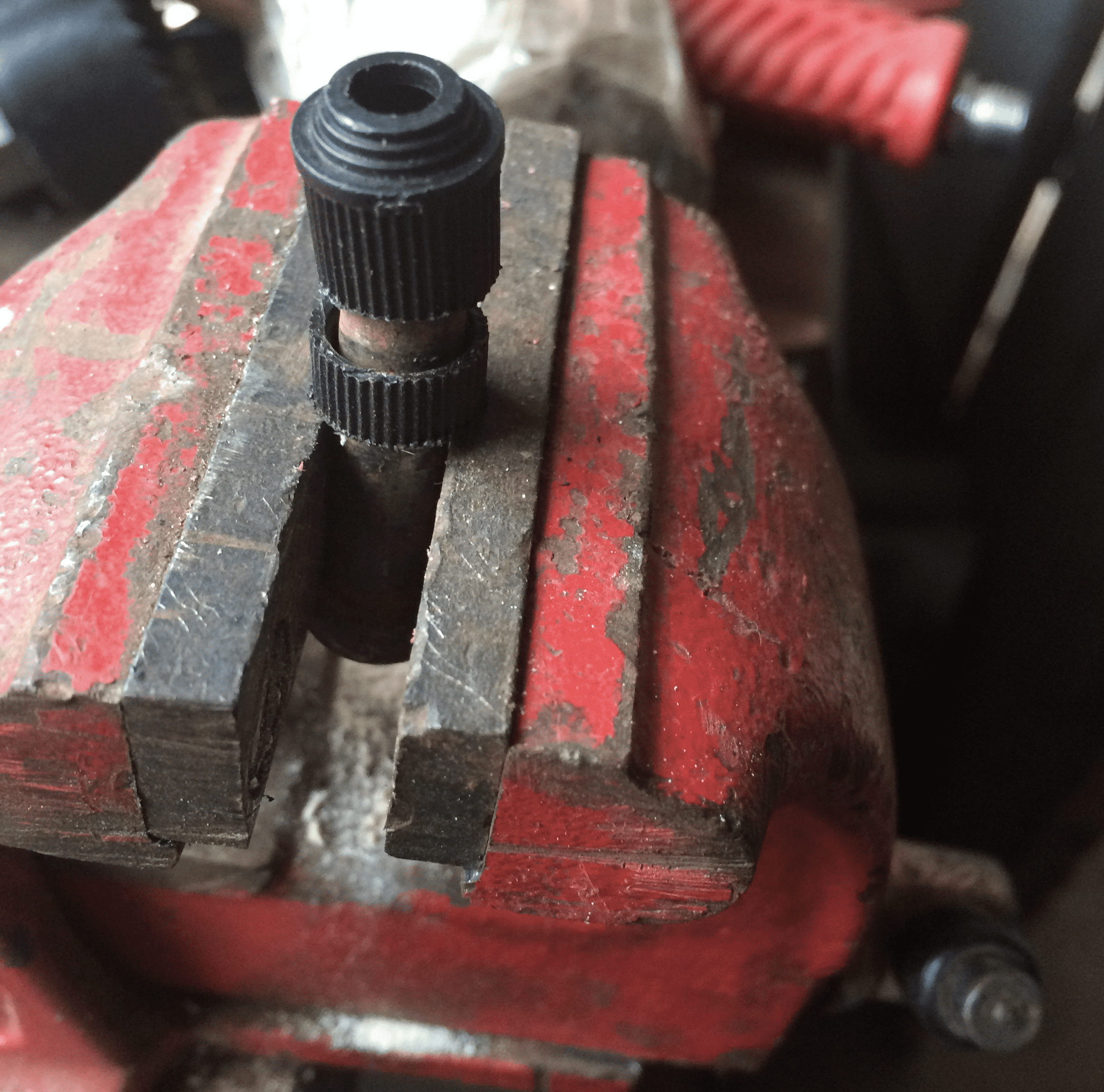
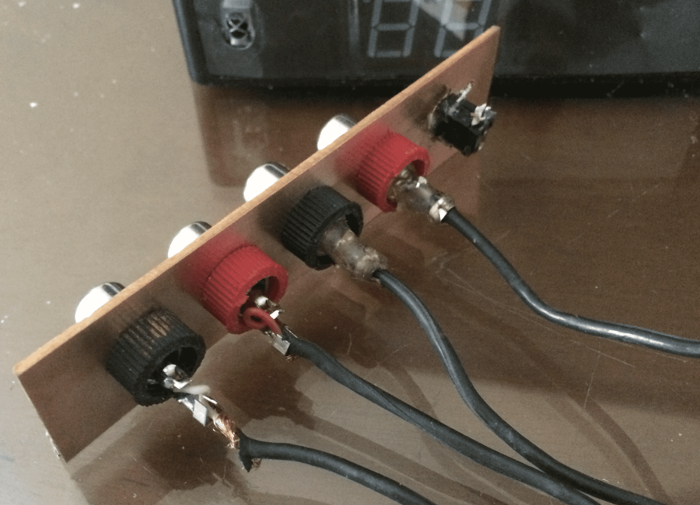
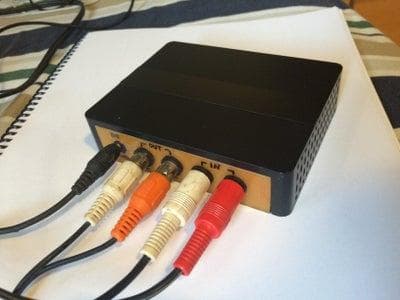
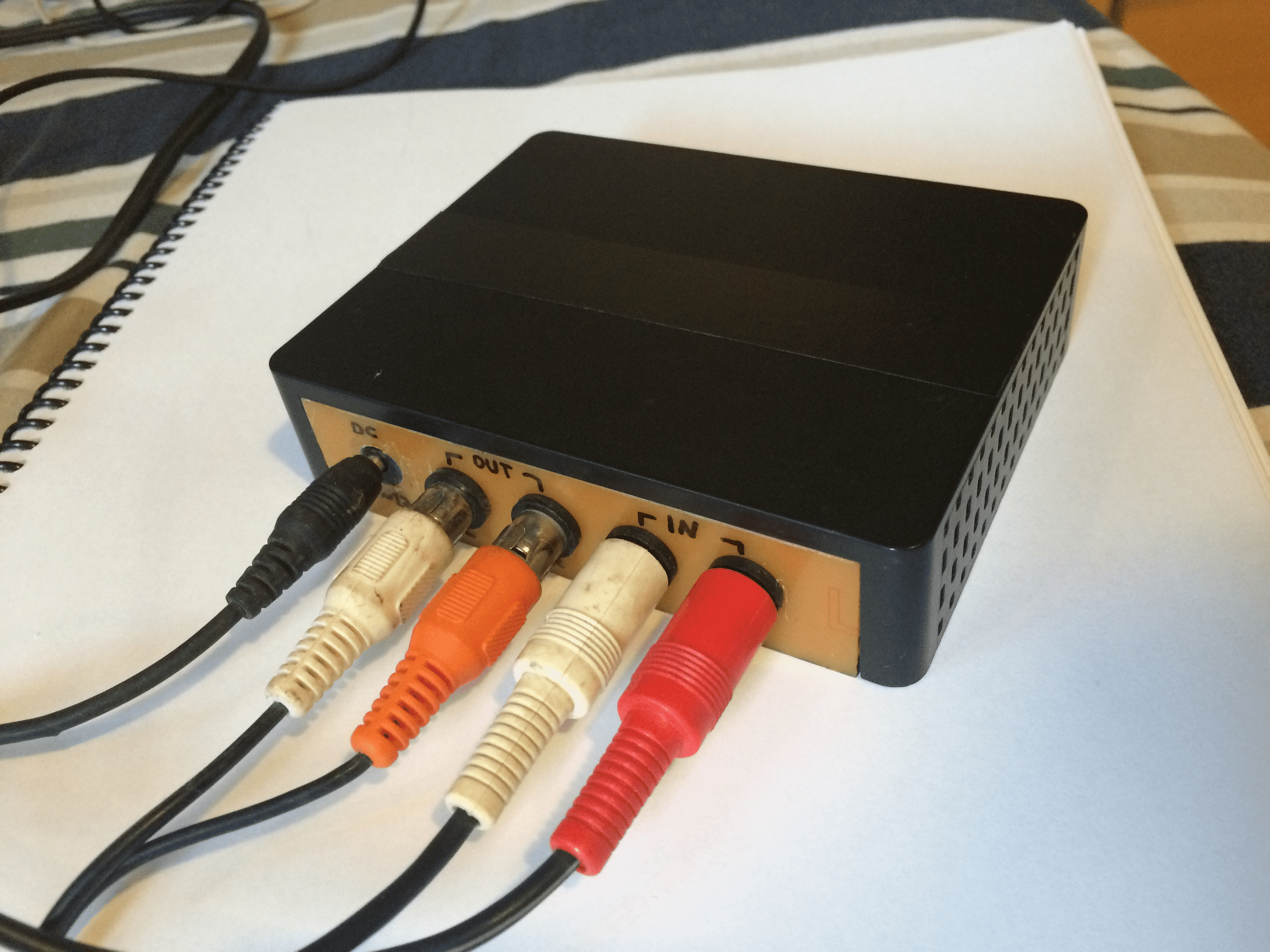
Step 11: Preparing the RCA Plugs
I cut the covers to make it neater, also put a bit of superglue to stop then rotating, when you try to plug a cable.
Step 12: Labeling
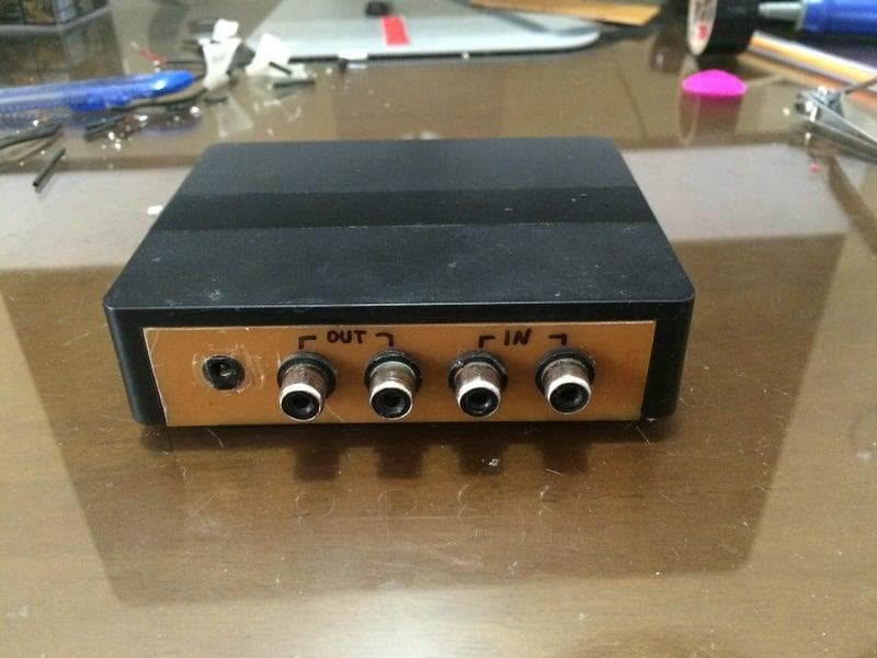
I used permanent maker to write the labels.
I could also print it on a sticker, but I don't bothered.
Step 12: Labeling
I used permanent maker to write the labels.
I could also print it on a sticker, but I didn't bother.
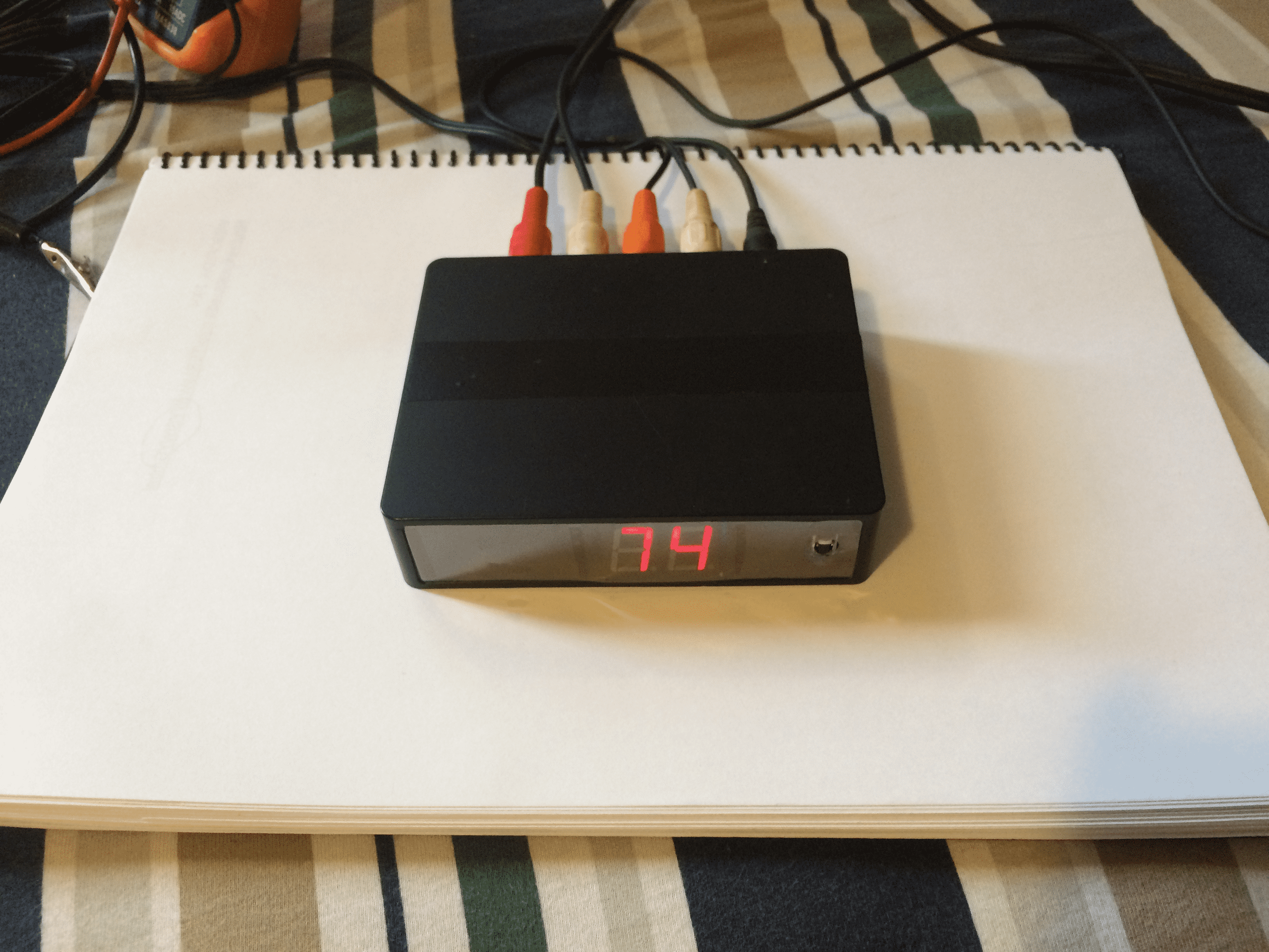
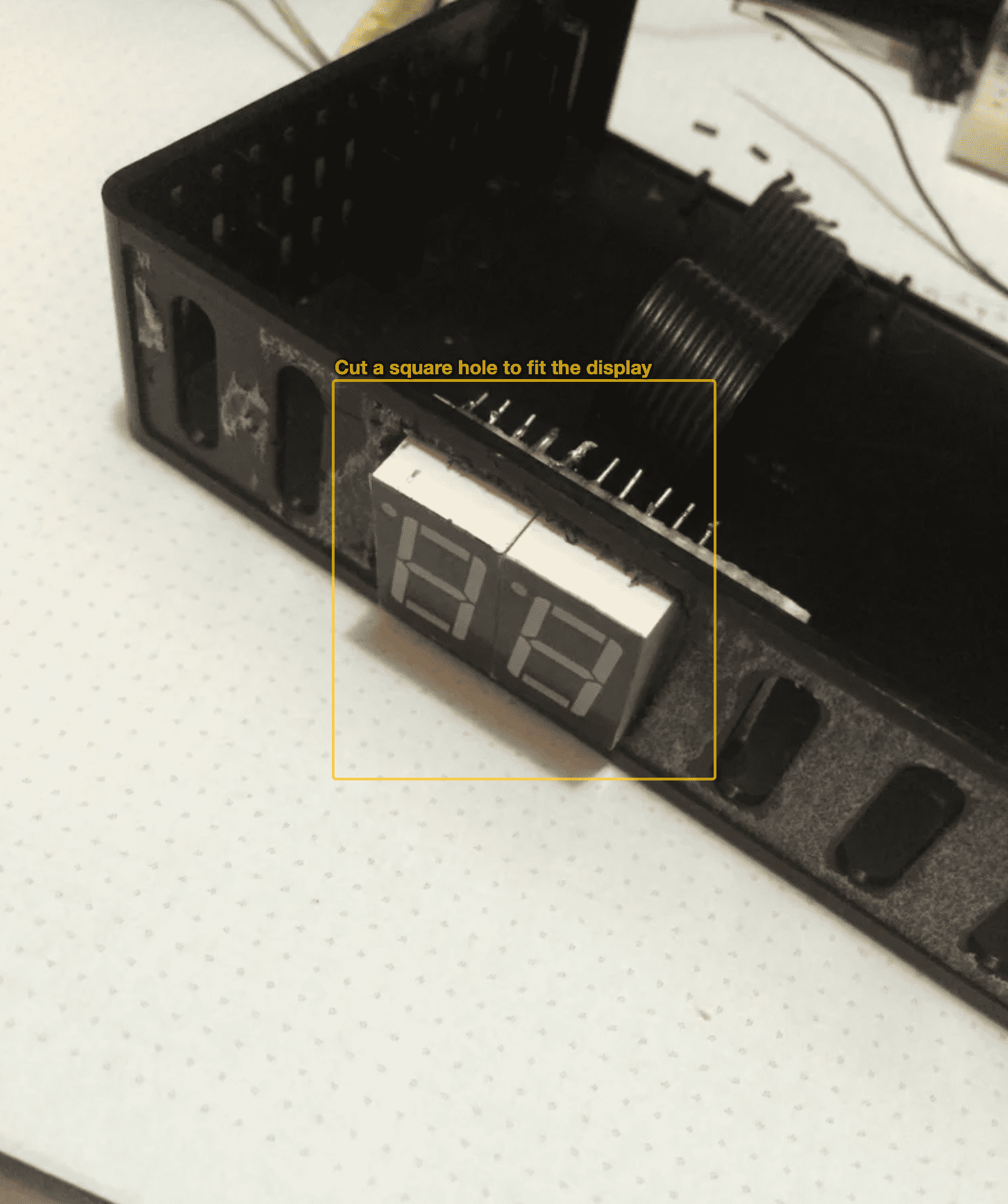
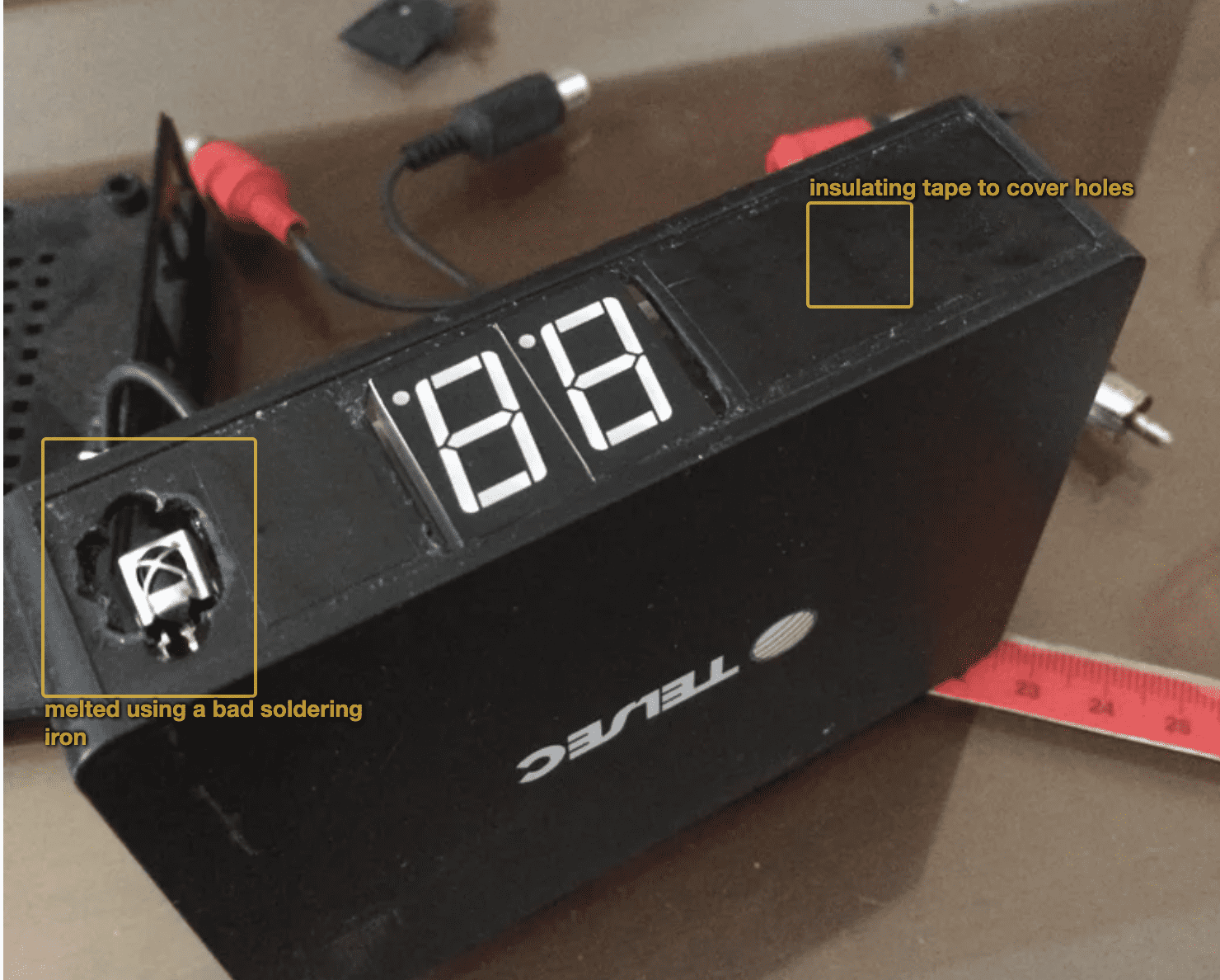
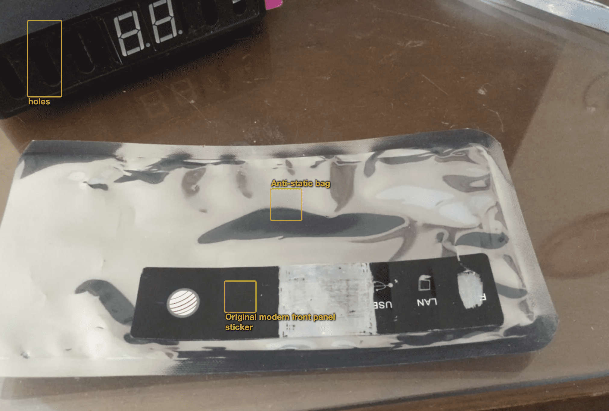
Step 13: Front Panel
The front panel was ugly.
I covered the holes with black tape, and used the original plastic as a mold to cut a piece of antistatic bag, that I found that was a bit opaque but let the light trough, but hid the imperfections.
I used a paper hole punch to punch a hole for the IR sensor. Mine wasn't very sharp, so the hole got a bit dented.
Then cut striped of double sided tape and sticked it on front.
I think it turned pretty good.
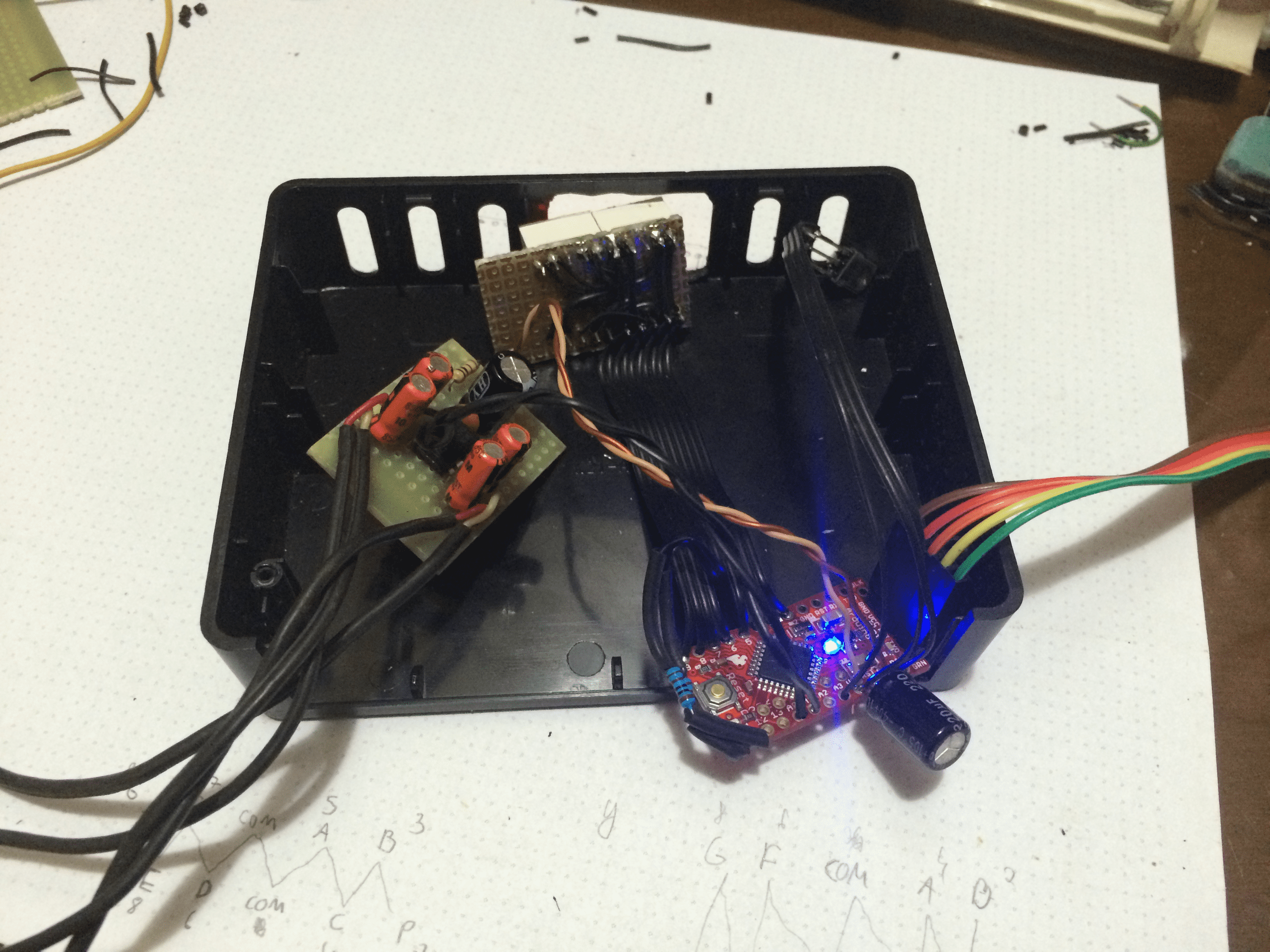
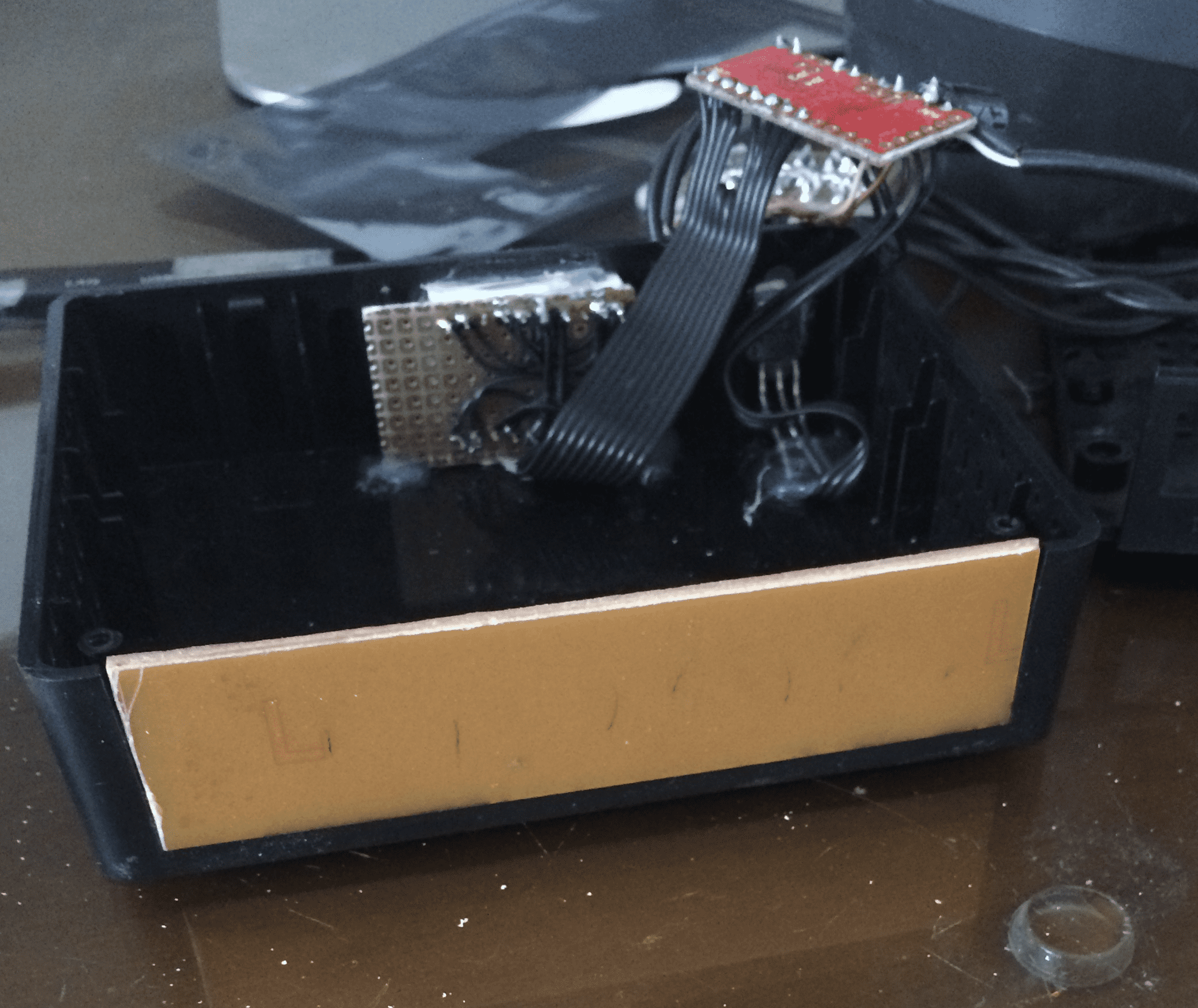
Step 14: Inside
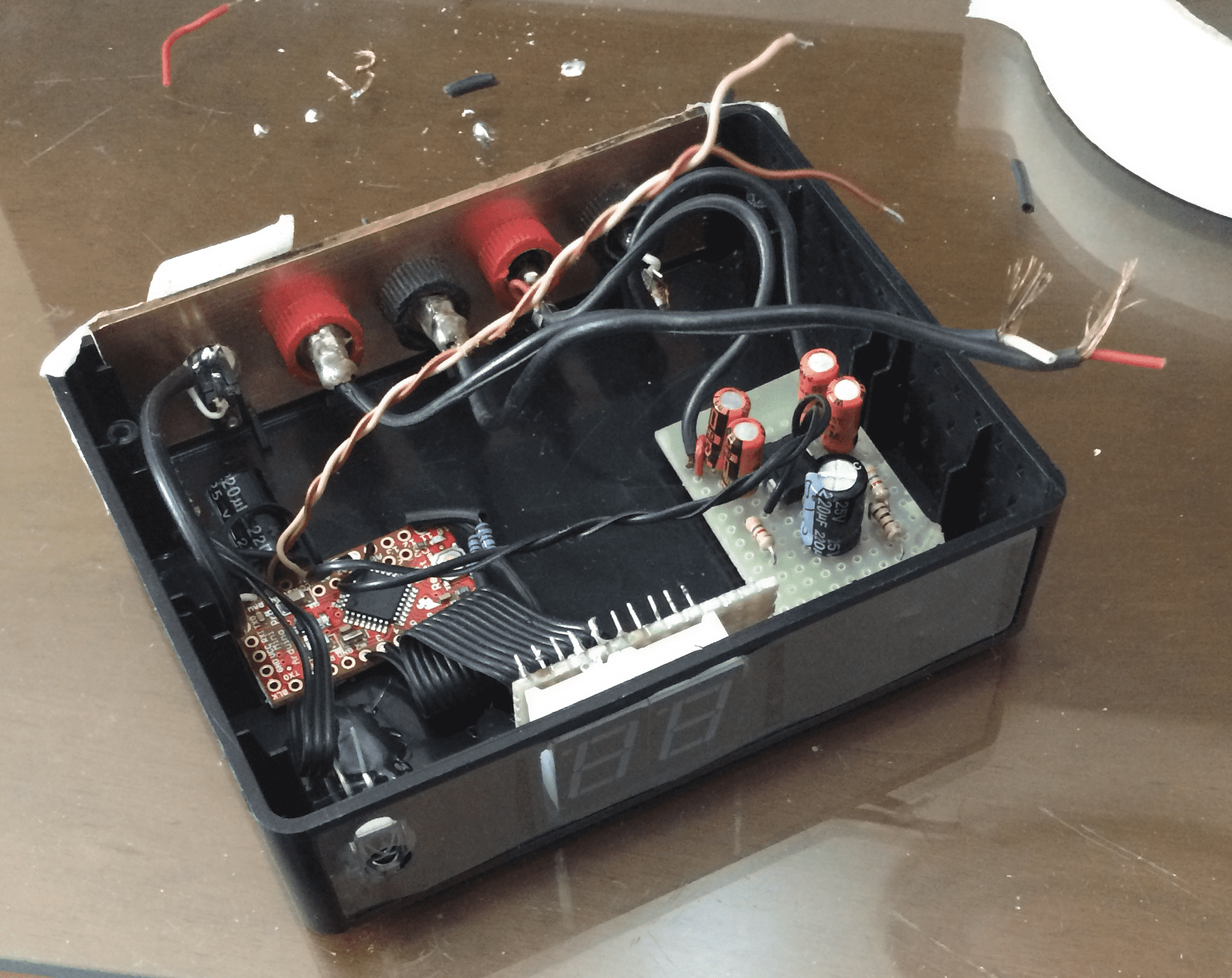
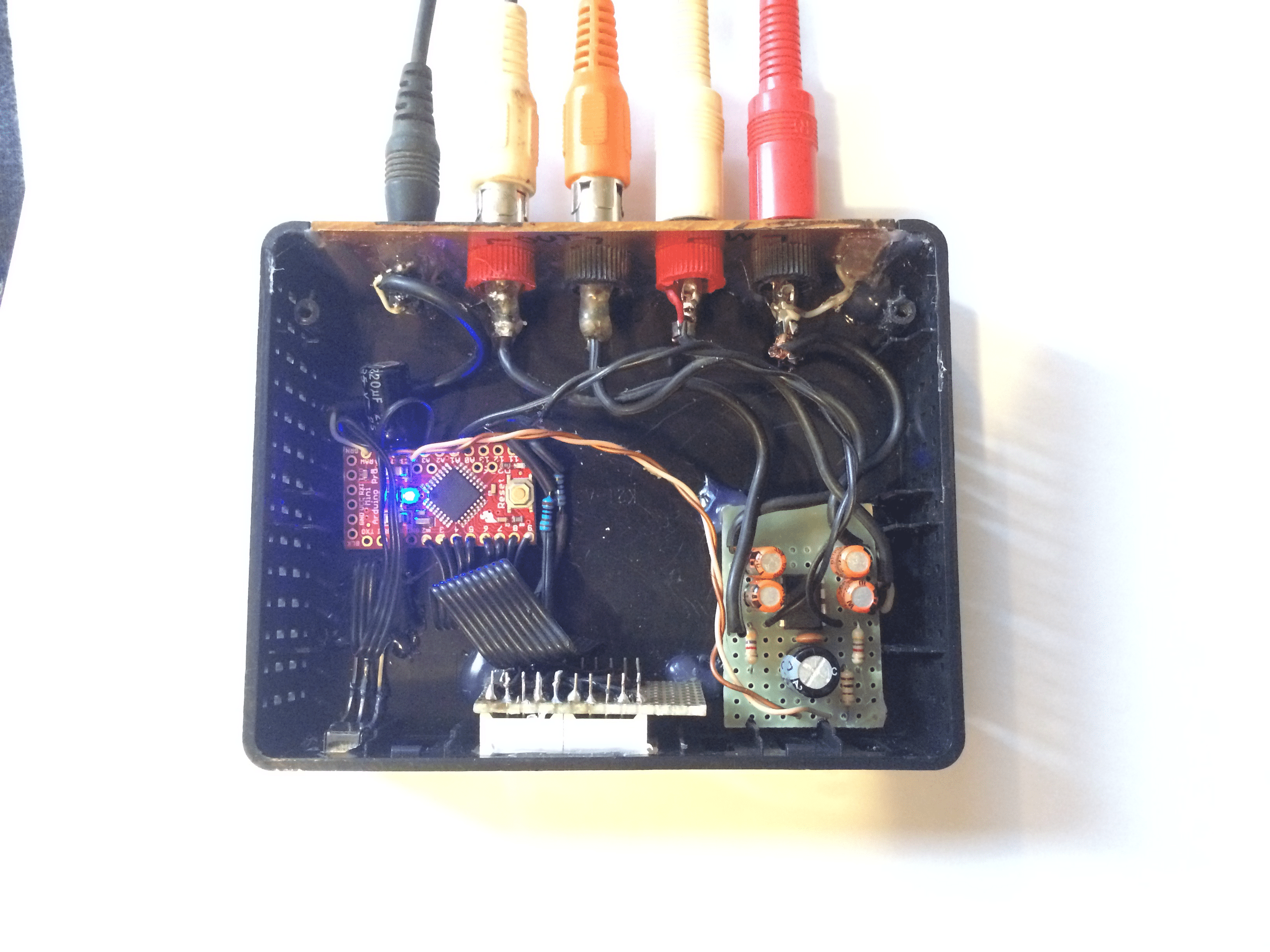
Hot glue and more hot glue.
For something like that, hot glue is awesome.
Just don't put too much, if you want to take something apart later without broking it. Just enough to hold everything in place.
Step 15: Programming
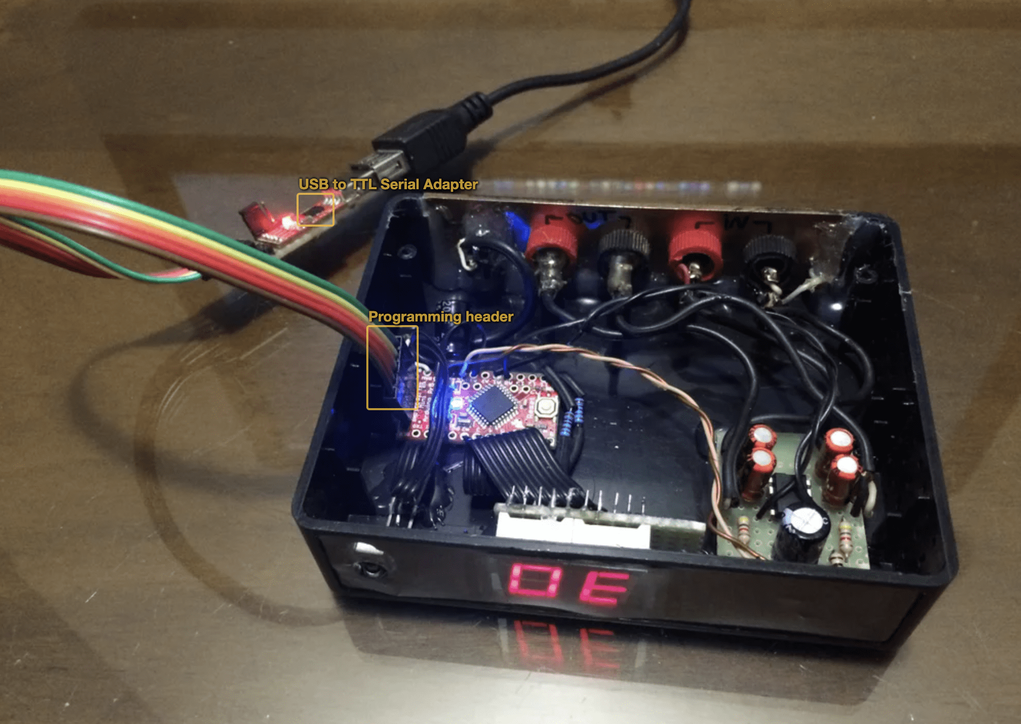
Just flash the firmware to it.
The code is fairly extensive, I will provide an overview of the full code.
Full firmware:
GitHub\ Contribute to victornpb/sketch_aug20b_som_remote4 development by creating an account on GitHub.\ https://github.com/victornpb/sketch_aug20b_som_remote4
displayRoutine.ino contains:
- ledBlink - handles led blinking and time out asynchronously
-
currentViewMode - one of the possible ones:
- VIEWMODE_NORMAL, displays the current volume, then switch to VIEW_IDLE
- VIEWMODE_ANIM_MUTE, alternate between dashes and the current volume in a defined interval
- VIEWMODE_ANIM_VOLUP, display the animation then switch to VIEWMODE_NORMAL
- VIEWMODE_ANIM_VOLDW, display the anim backwards then switch to VIEWMODE_NORMAL
- VIEWMODE_LOCKED, turn of the display, and turn on the decimal points
- VIEWMODE_IDLE, the display will not change it will display whatever is currently on the buffer.
- framesLenght and frames[][2] is the actual animation and length.
-
displayRoutine()
- function called on the main loop it will handle the timeouts and will call the sevenSeg_displayHold() that will display the data on the actual display.
sevenSeg.ino contains:
This arduino sketch provides software to drive 7-segments display with multiplexing, asynchronous, and doesn't not require external hardware or timer interrupts. Only a single segment is turned on at time, this allows the display to be turned with just the pins current, and only requires a single resistor per display on the common pin, also allows the display to use a fraction of the full power.
- sevenSeg_font[] array containing a bitmap that represent each digit
- displayData[] - byte buffer of each 7 segment display
- sevenSeg_setNumber() function that sets the displayData buffer with the correct sevenSeg_font bitmap
- sevenSeg_displayHold() Function that perform the multiplexing to draw every digit with a assyncronous delay between segments
EVC.ino contains:
Library for using PT2257 - Electronic Volume Controller IC.
- void evc_setVolume(uint8_t dB);
- void evc_setVolumeLeft(uint8_t dB);
- void evc_setVolumeRight(uint8_t dB);
- void evc_mute(bool toggle);
- void evc_off();
remote.ino contains:
- enum LgRemote
- enum AiwaRemote
- lgMenu
The UP and DOWN arrows are used to control the volume, but when the menu key is pressed, these keys are used to navigate the menu, this namespace is used to handle when a menu key is pressed and momentarly stops responding to the UP/DW keys to avoid conflict when navigating on menu.
- onModeLocked
- onModeLockedOff
- routine()
- processKey(unsigned long value, long currentMillis)
- byte processRemote() This function is called on every loop and handles and dispatch everything related to IR events
sketch_aug20b_som_remote4.ino
- enum Cmd { CMD_NONE, CMD_VOLUP, CMD_VOLDW, CMD_MUTE }
- byte mode
- State machine
I wrote the firmware in pieces that you may use if you want to make your own firmware:
Library for using PT2257 - Electronic Volume Controller IC:
Sketch with good pattern to use one or more remotes to execute actions:
This arduino sketch provides software to drive 7-segments display with multiplexing, no external driver required to drive 1 or a few displays. No hardware interrupt required, asynchronous execution:
Arduino example code to drive a 7-segments display, from a bitmap array:
Step 16: Done!